What I accomplished this week
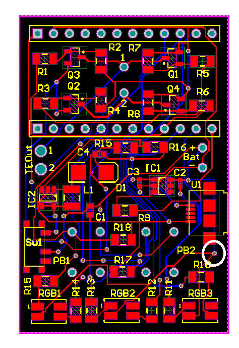
This last week, I was trying to identify where the problem was in my design that was causing the results that were outlined in the previous post. I thought I identified the problematic trace which is the one connected to the white circled via in the bottom right corner in the image below.
This is the trace that connects the common anode of the LEDS to the source voltage. The idea is that when you want to turn on one of the LEDs, you pull that signal pin LOW instead of HIGH and that will give the polarity needed to turn on the LED. However, as you can see from the image, this trace is not routed through the main power switch on the left (Sw1). I deduced that this was the reason why the LEDS are turned on even when the power switch is off. To reroute this without having to fabricate another board, I cut the trace and then placed a jumper between the circled via and the output of Sw1
Test, Observations, and Problems
Before rerouting the trace, I uploaded some code the microcontroller that told the LEDS to turn blue on startup. With the switch off, I supplied a voltage and the red LEDs illuminated just as before. When I pressed the buttons, the microcontroller powered up and the blue LEDs turned on so that was successful. So I then rerouted the trace with hope that would solve the problem of the red LEDS illuminating when the switch is off and it did, but then that lead to another problem. When the switch was off, everything was off, but when you turned the switch on, the power LED on the microcontroller flashed for a fraction of a second and then shut off.
Next Week’s Work
Next week, I’m going to compare my old schematic to the new one and then remove components one by one to identify which section of the board is causing the issue. I also need to submit my application to present at the Undergraduate Research Symposium.
Also, a message to all readers, if you see the problem with my circuit, comment!

