How do we code Agents? Before we begin building autonomous agents, we must understand what an agent can and cannot do:
- An agent has a limited ability to perceive the environment: An agent must have methods to reference other objects in the code. The extent to which he is able to interact with other objects is entirely up to us but will most likely be limited in some way just like living things.
- An agent reacts to its environment by calculating an action: Actions in this context are forces that drive the dynamics of the agent. The way we have calculated forces before is through vector math and this will be no exception.
- An agent is a follower, not a leader: Though less important than the other two concepts, it is important to understand that we are implementing code to simulate group behavior and dynamics. The trends and properties of the complex system depend on the local interaction of the elements themselves.
Much of our understanding for coding agents comes from computer scientist Craig Reynolds who developed behavioral algorithms to animate characters.
What we want to do with agents is create methods for steering, feeling, wandering, pursuing to give the elements life-like substance. These behaviors will use motion with vectors and forces.
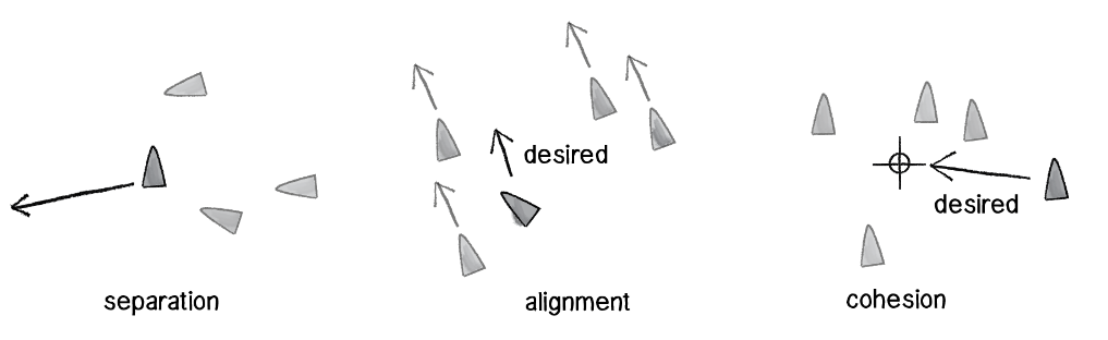
The agents of the system we will build will have limited decision making based on a series of actions. Most of the actions we seek to simulate can be described as ‘steering forces’. These steering behaviors can may include seeking, fleeing, following a path, following a flow field of vectors and flocking with the other agents. Flocking can be further dissected into the following steering behaviors: separation, alignment and cohesion. In order to get creative with this framework, it is our responsibility to mix and match different behaviors for the agents and see what kind of system we end up simulating.
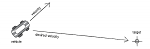
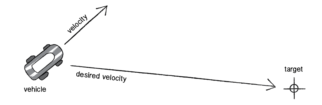
desired velocity
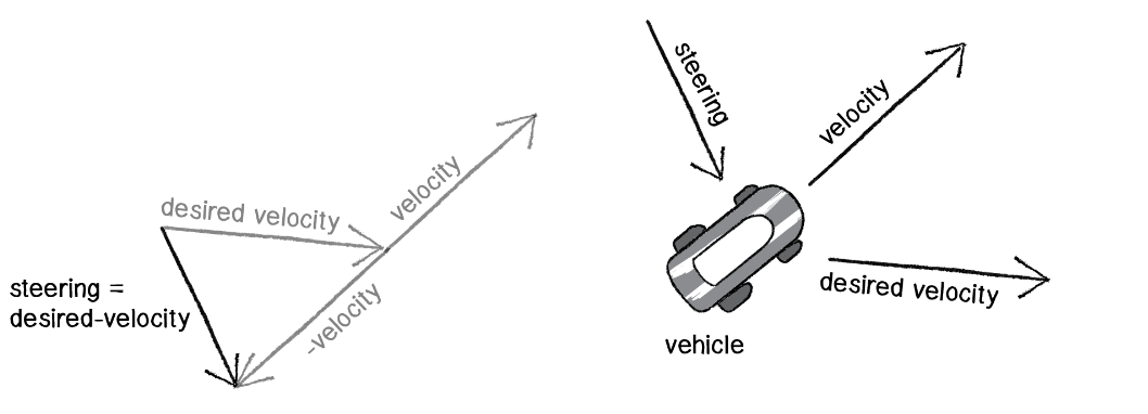
The most important concept is that of a steering force.
Steering force = desired velocity – current velocity.
So Pvector steer = PVector.sub(desired, velocity);
We use the static method of subtraction for the PVector class
PVector desired = PVector.sub(target, location);

Furthermore we must also limit the speed of this desired vector because otherwise the agent will move really fast and depending on how far the target is, it could just appear to simply teleport there. The other key point is that once we have the steer vector we must apply it to our agents as a force.
To do this we must write an applyForce() method
Void applyForce(PVector force) {
Acceleration.add(force);
}
We will use the standard Euler Integration motion method to update the agents’ position with velocity.
Another refinement for this method of steering is to use a limiting case for the velocity as the agent approaches the target, where velocity depends on the distance of the agent to the target. We can use an if statement with the magnitude of the desired vector:
// Distance from target to agent
Float d = desired.mag();
If (d < 100) {
// We map a range of values around a hypothetical circle of radius 100 around the target. Once the target gets to that area, its velocity values change from 0 to maxspeed
Float m = map(d,0,100,0, maxspeed)
Desired.mult(m);
} else {
Desired.mult(maxspeed);
Flock Behavior
Interesting systems can be created applying Reynold’s algorithm for steering to simulate particular group behaviors seen in nature. The three main behavioral methods in flocking are separation, cohesion and alignment.

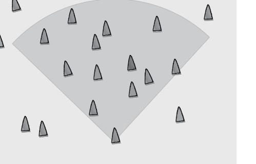
Separation
Separation is the method that gives agents the ability to evaluate how close they should be to their neighbors depending on the magnitude of the ‘separation force ’ we give them.
When dealing with group behavior, we are going to have to create a method that accepts an arraylist of all agents.
This is how we will write our setup() and draw()
ArrayList < Agent > Agents;
Void setup() {
Size(320,240);
Agents = new ArrayList<Agent>();
For (int I =0; I < 100; i++) {
Agents.add(new Agent( random(width), random(height)));
}
}
Void draw() {
For (Agent v : agents) {
a.separate(vehicles);
a.update();
a.display();
}
In our vehicle class we must create the separate method.
Void separate (ArrayList<agent> agents) {
// We set what we want our desired separation distance such that when any agents is this close to //another, we want vectors pointing away from each agent to influence their velocity.
Float desiredseparation = r*2;
PVector sum = new PVector();
// count of agents that satisfy the desired separation;
Int count = 0;
For (Agent other: agents) {
Float d = PVector.dist(location, other.location);
If ((d>0) && (d < desiredseparation)) {
//Define a vector from the other agent to the agent, in other words a fleeing vector
PVector diff = PVector.sub(location, other.location);
Diff.normalize();
// We divide the vectors by their distances so that if an agent is too close, it will flee faster than if it were near.
Diff.div(d);
// We add all vectors from all near agents
Sum.add(diff);
Count++;
}
}
// Now we can apply our steering behavior so that the vectors in sum become the desired vector for the agent.
If (count > 0) {
// We are looking for the average of all the fleeing vectors
Sum.div(count);
Sum.normalize();
Sum.mult(maxspeed);
PVector steer = PVector.sub(sum, vel);
Steer.limit(maxforce);
applyForce(steer);
}
}
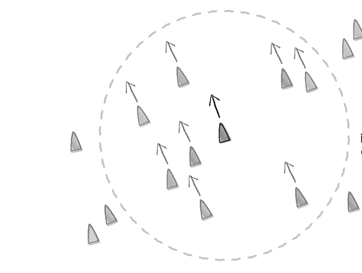
Alignment
Alignment is the behavior of agents that makes them want to steer in the direction as the other neighbors. Cohesion is the behavior that steers the agent towards the center of the other neighbors.
For alignment,
PVector align (ArrayList<Agent> agents) {
Float neighbordist = 50;
PVector sum = new PVector(0,0);
Int count = 0;
For (Agent other : agents) {
Float d =PVector.dist(location, other.location);
// If the distance is less than a predetermined quantity, initiate vector collection.
If (( d>0) && (d<neighbordist)) {
Sum.add(other.velocity);
Count++
}
}
If (count > 0) {
Sum.div(count);
Sum.normalize();
Sum.mult(maxspeed);
PVector steer = PVector.sub(sum,velocity);
Steer.limit(maxforce);
Return steer;
} else {
Return new PVector(0,0);
}
}
Cohesion
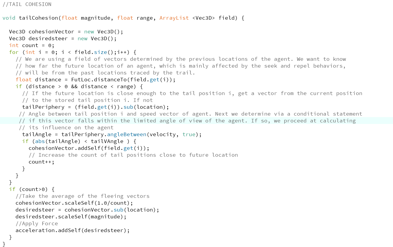
Last but not least, we must code the cohesion behavior. Cohesion is sort of an attractive steering force. We may call this a seeking behavior which looks for the average location of all neighboring agents and applies a velocity steer vector based on the location of the agent and this target. So we code the seek behavior and then reference the seek behavior in the cohesion method.
PVector seek(PVector target) {
// Make a vector from the agent to the target, which will be fed by cohesion method.
PVector desired = PVector.sub(target,loc);
Desired.normalize();
Desired.mult(maxspeed);
PVector steer = PVector.sub(desired, vel);
Steer.limit(maxforce);
}
Now we can establish our cohesion method:
PVector cohesion (ArrayList<Agent> agents) {
Float neighbordist = 50;
PVector sum = new PVector(0,0);
Int count = 0;
For (Agent other : agents) {
Float d = PVector.dist(location, other.location);
If ((d > 0) && (d < neighbordist)) {
Sum.add(other.location);
Count++;
}
}
If (count > 0) {
Sum.div(count);
Return seek(sum);
}else{
Return new PVector(0,0);
}
}
With aseparation, alignment, and cohesion, we can begin to create our first flocking algorithm