mat[3].z != mat[2].z

The reflection matrix math did work, however I updated the wrong column ….

Anyway, mirrors are now implemented in the VizHome viewer:

Virtual mirror

A virtual mirror (some 4×2 meters) inserted into the Ross’ House dataset on the Z-plane for debugging.

The mirrors currently render only the bounding boxes of the hierarchy; rendering the actual point cloud data leads to crashes. My current guess is that in the multi-threaded environment, some voxels get unloaded in some threads (because they are now longer visible) while other threads still try to access them.

Generally, the difference between having mirrors and not having them is already pretty interesting:

Mirror enabled

Mirror enabled

Mirror disabled

Mirror disabled

An additional clipping plane is required and has to be implemented in the shaders, otherwise objects in front of the mirror might get projected into the mirror image. This might require changing all vertex shaders, however maybe rendering the mirror contents might have a dedicated shader.

As a side note: using occlusion queries to update visibility information does not work either:

Occlusion query disabled

Occlusion query disabled

Also note that all the mirror FBOs in these images are quite low-res at 256×256 pixels. Current optimizations are: disabling update and rendering if the mirror is not visible (simple viewfrustum culling in projection space), if it is facing the wrong direction and hopefully if it is fully occluded.

Next steps will be rendering of the actual point cloud data and looking at it on the dev wall and maybe in the CAVE to see how the mirrors  ‘feel’.


Experiments with Muscle Wires

I’m fortunate to be able to tie my current research into an upcoming site-specific exhibition piece, which will be shown at the offices of Life technologies, a local stem cell research lab.  When we toured their facility, we were shown some amazing video of cardiac cells independently pulsing in a ring format.

CardioVortex_4XThis has become my inspiration point for the installation.  It is my hope to use muscle wires to create the pulsing effect on my printed textile, potentially tied to some sort of motion sensor or other input.

In order to gain a familiarity with the basics of muscle wires, I completed the Origami Flapping Crane tutorial provided by MIT’s High-Low Tech Lab.  This was a great little project that very successfully illustrated the basic use of Flexinol wire.

https://www.youtube.com/watch?v=wQKggIUqx0s

With that success under my belt, I started experimenting with ways to utilize the muscle wire’s contracting properties to create the pulsing circles on a textile (most likely felt in this case).  One of the core issues with Flexinol is that while it contracts when heated, it does not return to it’s original length when cooled.  An opposite force of some kind must be applied.  In the flapping crane example, the stiffness of the paper is enough to pull the wire back into shape.  A little research led to the suggestion of using music or piano wire as a kind of spring, both to actuate the fabric and to return the wire to it’s original length.

My first spring concept:

SpringOneThe red lines show where the muscle wire would be attached.  This arrangement would allow the muscle wire to contract the music wire while maintaining a circular shape.  Unfortunately, the music wire I chose was far too strong for this application and the muscle wire was unable to move it.  On a whim, I tried a more low-tech option and just sewed the wire onto a piece of felt in a similar arrangement to see what happened.

FeltTestThe results were also less than successful.  Apparently one of the other limitations of Flexinol is that the overall change in length is very small, along the lines of 5-7%.  So while this arrangement moved the fabric, it didn’t move it very far.

My next step is to modify my plan based on these outcomes.  I am going to purchase much thinner music wire to use as my spring.  I am also going to break the muscle wire down into smaller length attached to each segment of the spring, as opposed to one continuous piece.  I think this will help me to maximize the movement potential of the Flexinol.  Also, this will potentially give me more control options over the final movement effect.

Sculpting now working

Over break, Kevin & Ross helped me out tremendously by getting the stylus to now sculpt a model in the world builder application.

photo


I believe the IPD may need to be slightly adjusted so that you cant see two images. This should be an easy fix, though.

My next steps are now to use the leap motion to grab and rotate the object on screen.

I will add more to this post this week as I work into integrating the leap motion into the world builder application.

ReKinStruct: Switching Between PCDs

This week, I tried to switch visualising between two PCD files to check if it was feasible in run-time and to know how long it takes for the process. The following were the two PCD file visualisations I was trying to switch between: couch with the box and without the box.

With Box

Without Box

I tried doing this by two methods.

Method1) Load both the PCD files initially into cloud pointers. Display one and switch to another on the click of a button.

Method2) Load one PCD file and display it. On the click of a button, clear the current pointer, load the other PCD file and display it.

I am attaching videos to show how fast the process was.

Simultaneous Load: http://youtu.be/tFJUoOFaGcY

Sequential Load: http://youtu.be/77-9w1rnUyA

I have loaded the Point Cloud Data without the colours (PointXYZ as opposed to PointXYZRGBA) on purpose to get a feel of the point cloud. Also please note that the time taken to switch between the point clouds is the time from when I click ‘s’ to the time it prints ‘Changing point clouds’ on the console. ‘Changing’ would have made more sense if it was ‘changed’. My apologies.

The main observations were:

1) Switching between PCD files that have already been loaded into memory was faster than loading it from the disk.

2) Loading more PCD files into memory will require a lot of RAM space. There was a mild increase in memory used in the Task Manager during Method1 than Method2 window because only two files were loaded now. I suppose there might be a scenario where we would need to switch between ten or more PCD files that might end up using a large chunk of the main memory.

The moire pattern on the wall that was far from Kinect was due to poor resolution of the Kinect with respect to distance. The coloured pictures on the top show the same PCD files without the Moire pattern as the display windows are small and hence the reduced resolution.

This week I am going to try getting more PCD files from an interesting scenario and try switching between them automatically. I hope the video looks interesting. Will keep you posted.!

Note: An interesting find was that the pcd_viewer_release.exe always loaded my PCD files in a rotated axis. I had to almost rotate the point of view by 180 degrees on the Z-axis to view the data. However, the pcd visualiser class loads the data as how the PCD was recorded ( in our case, the snapshot point cloud data). In cases where we need to rotate the Point Cloud Data while opening, the pcl::transformPointCloud() could be of use.

ReKinStruct: Obtaining Kintinuous PCD

Last week, I focussed on fixing the Kinect and started obtaining Point Cloud Data. This week I have obtained a continuous PCD using the SCENECT software. The SCENECT software is fairly easy to use and complements for not having KinFu. It obtains data from the Kinect and forms a 3D PCD by registering the frames as we move the Kinect.

Scenect Scan

The window on the right shows the frame that is being currently read from the Kinect and the window on the left shows the registered PCD. The yellow and green points on the right show the registration checkpoints for the frames. In my opinion, it is fairly good for registration and colour values. However, scanning and registration take a bit of time. For example, as you can see from the small window on the extreme left, it took around 2600 frames to register this small point cloud data. I have not worked with KinFu so I do not have anything to compare against but all in all, I think it is a good GUI to obtain data. It also offers a lot of post-processing options which I will try to figure out this week.

Below is the final PCD obtained from the scanning. Scenect Final

However, SCENECT does not readily allow us to export the scan points as a .pcd file. The easiest way to go around this is to save it as a .xyz file and write a program that reads every line containing XYZRGB values and write a .pcd. There are two ways to do this:

1. Based on the tutorial from http://pointclouds.org/documentation/tutorials/writing_pcd.php. For this method, you need to know the number of points in the cloud beforehand. This essentially means that you go throughout the .xyz file twice: first to know the number of points to create the cloud of the necessary size; second to read in the values from the .xyz file

2. The easier and the simpler solution is to just create a cloud pointer as

pcl::PointCloud<pcl::PointXYZRGB>::Ptr cloud;

and push_back the points as and when read from the file.

( I do not know why pointclouds.org has not written the tutorial based on the second method )

On a parallel note, I also tried playing around with the OpenNI grabber to obtain PCDs. The salient difference in using this method is that it saves a .pcd of the one frame that is being read from the Kinect at that instant of time. Thus, there is no possibility of registering frames and making a huge point cloud. For a start, I read the frame as

OpenNI Viewerand the PCD file that was saved appears something like

PCD Viewer

That is the couch and the air conditioner nearby saved as a point cloud and viewed using the pcd_viewer_release.exe given by PCL. Though this method of obtaining PCDs doesn’t have a  potential advantage over the SCENECT, the OpenNI grabber PCDs can be used to obtain time varying PCD frames. That will be my goal for the upcoming week. Try to obtain time varying point clouds (like a candle melting) and switch through them. The dream would be to switch through ‘n’ number of point clouds fast enough that it will appear like a 3D movie.! Sounds cool, right?

More mirror stuff

Implemented mirrors with reflections about arbitrary planes at arbitrary distances from the origin. The math runs something like this:

Let R be the Reflection matrix (see Essential Maths for Games, pg152), then the combined matrix R‘ is: R‘ = T x R x inv(T) with T being the translation matrix of the mirror.

The complete matrix pipeline for the mirrored content is then: P x V x R‘ x M, with P=Projection matrix, V=View matrix, R‘ as above and M = Model matrix. It’s interesting that the reflection matrix sits between the model and the view matrix and it makes local transformation of objects easy: we just have to modify the Modelview matrix and can chain the object’s transforms regularly.

In the current (test app) it looks like this:

Virtual mirrors

Virtual mirrors

The big mirror is artificially defined and reflects the ground grid perfectly. The other mirrors are loaded from the detected mirrors in Ross’ house. As their angle is slightly offset, their reflection appears offset as well.

Empty mirrors are strange, so I implemented a very simple billboarded Avatar:

Avatar in mirror

Avatar in mirror

The matrix chain is similar to above, except that the resulting upper-left rotation-scale matrix is set to identity before multiplying with the projection matrix.

I also tried recursive mirrors. This should be not very expensive with this method, as each reflection is just a texture access. However, there was a strange rendering and transformation issue so I dropped it for now.

The VizHomeOOC rendering core has been modified quite a bit and now supports distinct rendering passes. Next week should see the merging of mirrors and the current rendering core. At the same time, I am looking into taking live video-feed from a kinect and streaming it onto the billboard as some kind of augmented virtuality system.

VRPN Zspace

Last week I was focused on making a function that would allow track the orientation of the stylus with position matrix. But while digging through the ZSpace SDK I noticed that VRPN supports ZSpace. This is really good news because now the stylus should work right away and we don’t need to worry about implementing a function that calculations the orientation of the wand. This week I will be attempting to tie all of the loose ends together and get the stylus fully functioning in the worldbuilder application.

A problem that I’ve come across is within the config file for Fiona. Since the Zspace is tilted at ~45 degree angle from the table, I need to calcuate where the x,y,z points are with respect to the screen and the angle in which it sits. The problems lies with in the config file, the format is: wall x y z width_x width_y width_z height_x height_y height_zThe wall is referring to the screen and how it is position. But when I run this I get nothing but a blank screen. It could be that my calculations are off (hopefully) or otherwise it will take some more digging to find the reason for this problem.

I don’t have much for pictures this week considering most of the tests are mostly code driven and don’t show much for outputs. But the image below represents x,y,z axis’ of a titled ZSpace screen.

photo

ReKinStruct- PCD: Check

After a bit of an initial struggle to set the Kinect up with the laptop, I have finally obtained Point Cloud Data.

First PCD

Yes, it is Alienware. Yes, I got my hands on the beast.

So, the visualisation window on the screen shows the frame that is being read from Kinect. The program as of now keeps adding XYZRGBA points to the temp file and saves it as a .pcd file when I press the ‘s’ key and continues to obtain the next dataset. This is just a basic program that I used to test if the Kinect was working.

However, this also gave me the idea to obtain and save PCDs periodically as discussed in the earlier posts. I have not yet tried exploiting all possibilities with the existing code like how big a file can it write, how long can I keep it running to obtain data, how good is the Kinect when it joins frames etc. The plan for the upcoming week would be to try exploring these areas.

Meanwhile, Dr.Ponto suggested the ‘SCENECT’ software which uses a GUI to obtain and modify the frames obtained from the Kinect. That would be a good idea to try along with the existing PCL visualisation code.

Will keep you posted.

Over and out.!

ReKinStruct: Installing PCL, OpenNI and other Kinect Dependencies on Windows (Tutorial)

Since I couldn’t find a simple and direct tutorial on the internet that helps compiling PCL, OpenNI and its related dependencies on a Windows machine, here goes one. Before this begins, a few clarifications.

  • Why use a Windows OS? Because I have a Kinect-for-Windows. If you are having a Kinect 360 that would work on other Operating Systems, I would suggest trying that in Linux before switching to OSX or Windows.
  • I tried installing KinFu too but had to quit as there were a lot of path errors in the CMakeLists. So, if you want KinFu specifically, I am afraid this post would not help you much. You could try installing KinFu with some help from http://pointclouds.org/documentation/tutorials/compiling_pcl_windows.php which is the official documentation and has the kinfu app extensions (See section Downloading PCL Source Code). Best of Luck!
  • If you want to try Kinect Fusion(Microsoft’s version of the same), this post is so tally not going to help you. Installing Kinect Fusion essentially means cutting off all ties with PCL and its dependencies. So, again, Best of Luck!
  • Stick to one architecture for all installations. Since most computers these days have a 64-bit architecture, we will use the 64-bit versions for all installation packages. *If you are having a computer with a 32-bit architecture, I think it is high time you get a time machine. You have so got to travel in time.*
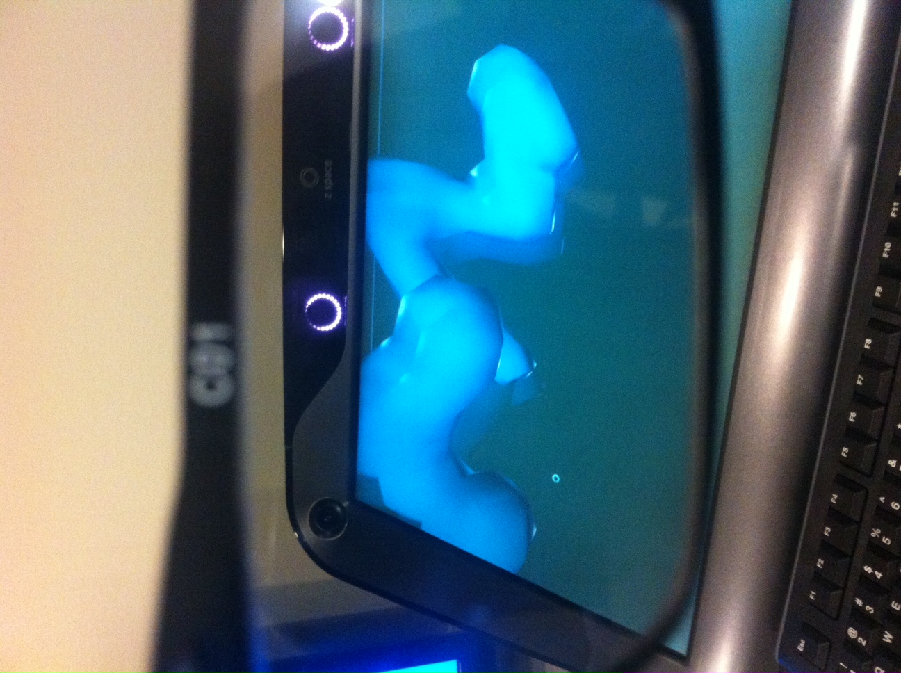
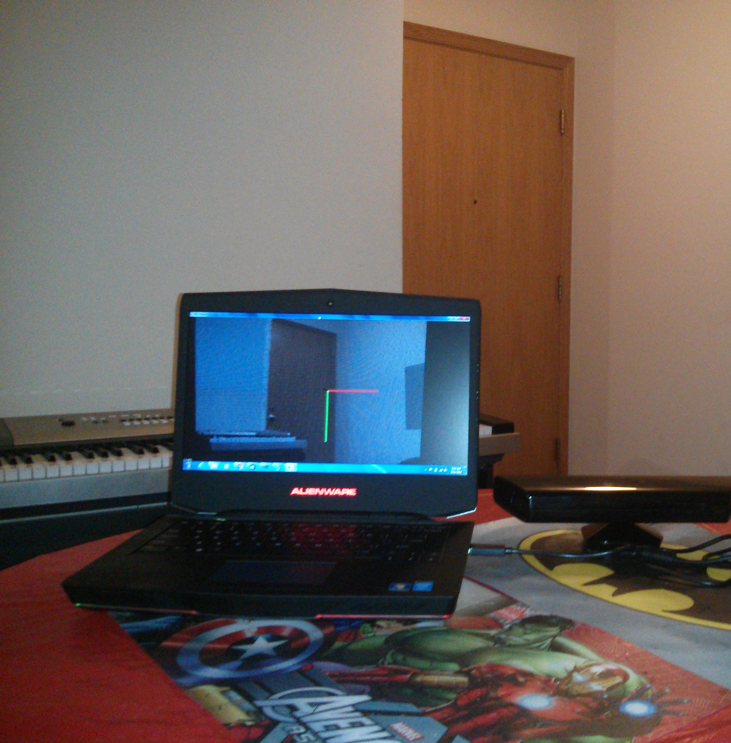
  • You need a good graphics card. I used an Alienware laptop with a NVIDIA GeForce GT 750M graphics card.

Step 1: Basics

Get Microsoft Visual Studio 2010 from www.dreamspark.com (if you are a student, you get it for free) or get it online. It has been one of my favourite IDEs and I hope you will find it useful too. The setup installs only a 32-bit Visual Studio package. You can change it to 64-bit Debug/Release mode by choosing Build->Configuration Manager->Active Solution Platform and changing it to x64 from Win32.

Step 2: Installing PCL

Installing PCL should be fairly straightforward. You can download the setup executable  from http://pointclouds.org/downloads/windows.html. Download the Windows
MSVC 2010 (64bit) All in One Installer. During installation, the setup will ask for the 3rd party dependencies it needs to install. Select Boost, Eigen, FLANN, Qhull, VTK. Uncheck OpenNI. We will install OpenNI in the next step from a different source. Redirect your directories in Visual Studio to point to the PCL files locations(PCL and every 3rd party dependence have their own bin, include and lib files).

Step 3: Installing Kinect Drivers

Okay, this is where it gets tricky. You need one (and only one) type of driver for the Kinect. Since we are going to stick to OpenNI, Do not try installing Microsoft Kinect SDK or KinFu.

Install OpenNI-Win64 from http://www.openni.org/wp-content/uploads/2013/11/

Install SensorKinect-Win64 from https://github.com/avin2/SensorKinect/downloads

Install NITE-Win64 from http://www.openni.org/wp-content/uploads/2013/10/

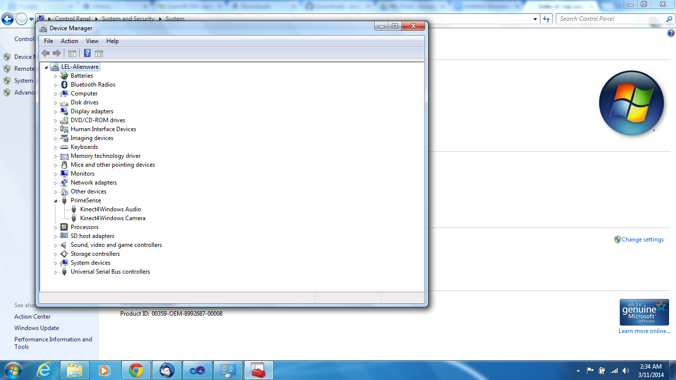
Try installing the latest versions of these Drivers. After installation, you should be able to see Primesense in your Device Manager with the Kinect Hardware as shown below.

Device Manager Primesense

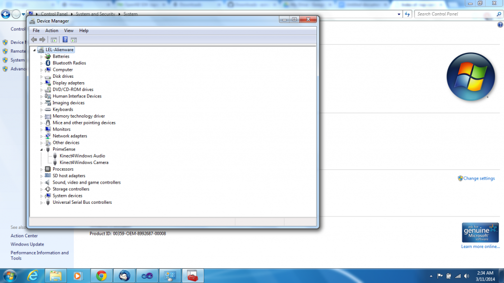
If it does not appear so, it means the Drivers did not sync with your hardware. Try going to an older version of the Drivers. I have OpenNI 1.5.7.10, SensorKinect v5.1.2.1 and NITE 1.5.2 which are not the latest versions but these are the ones that work on my computer.

Step 4: Verification

Connect the Kinect to your laptop. Select Start->OpenNI 64-bit->Samples->NiViewer64. If step3 was successful you must now be able to see your Kinect reading in data (both depth and colour). I guess you can have a sigh of relief at this point.

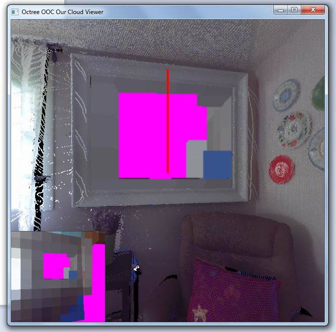
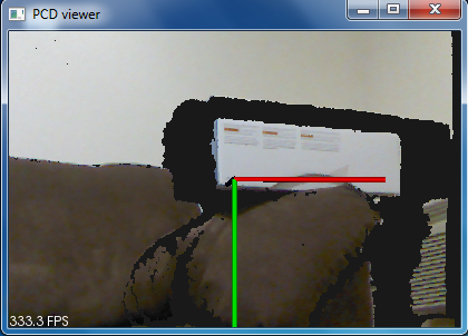
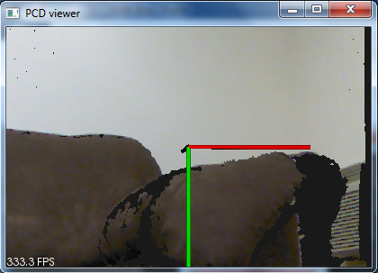
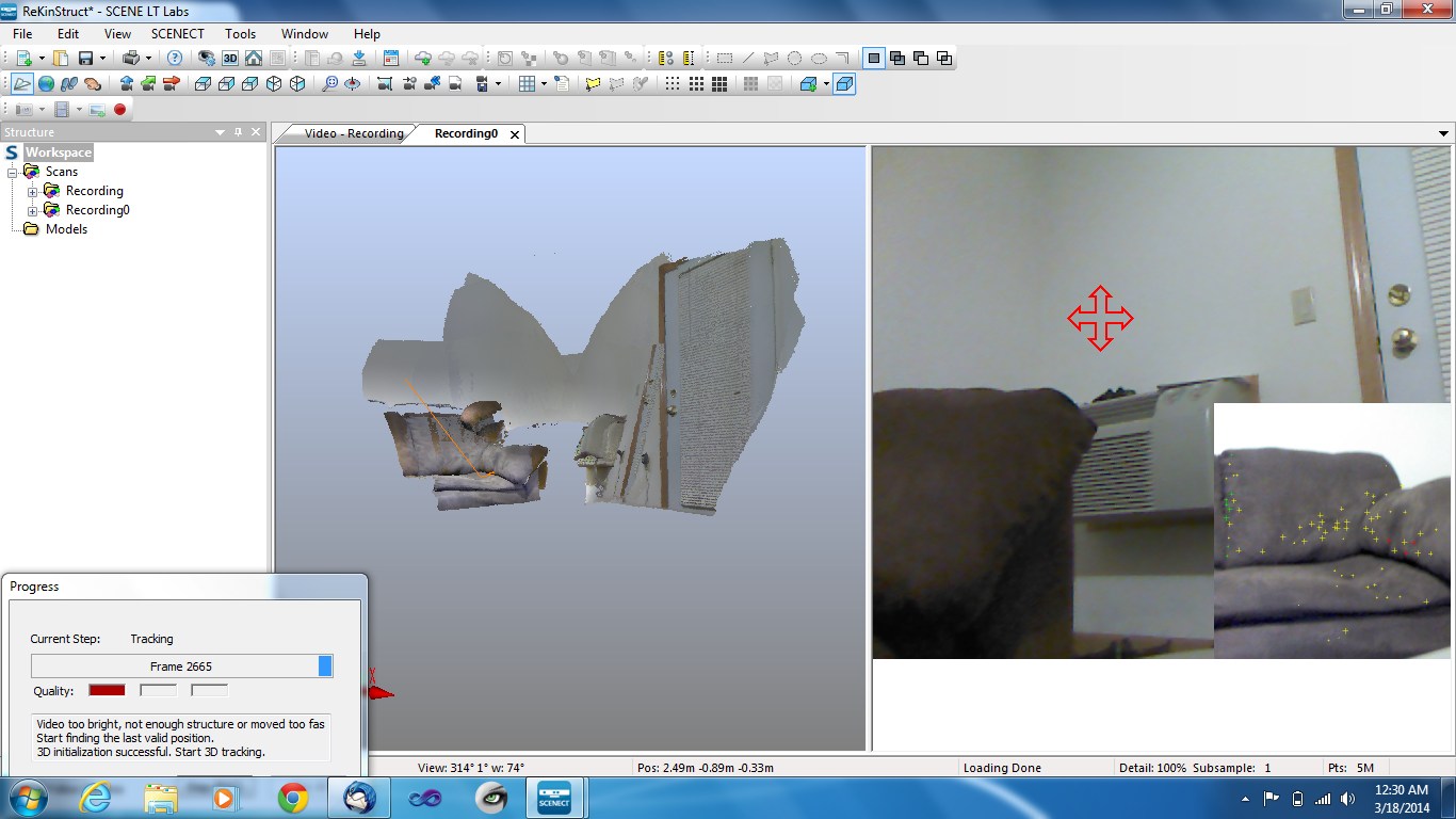
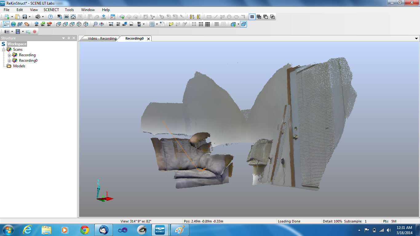
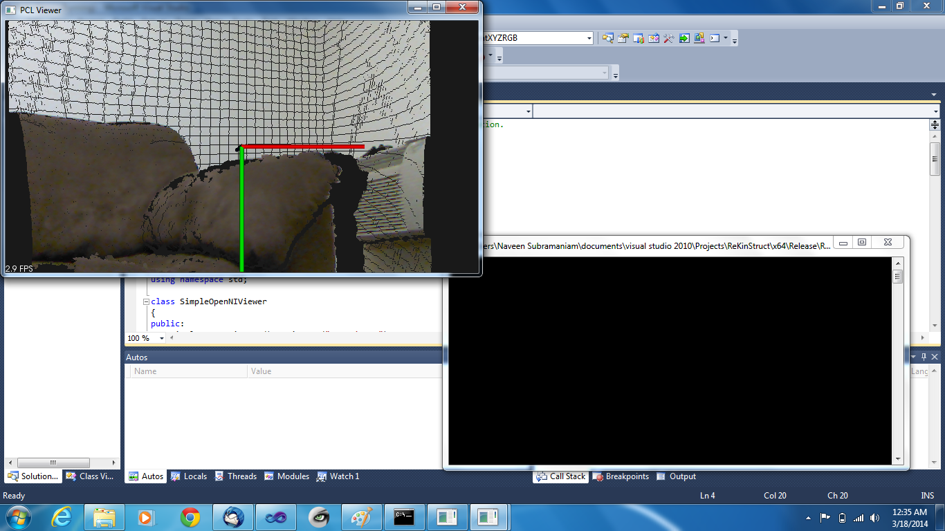
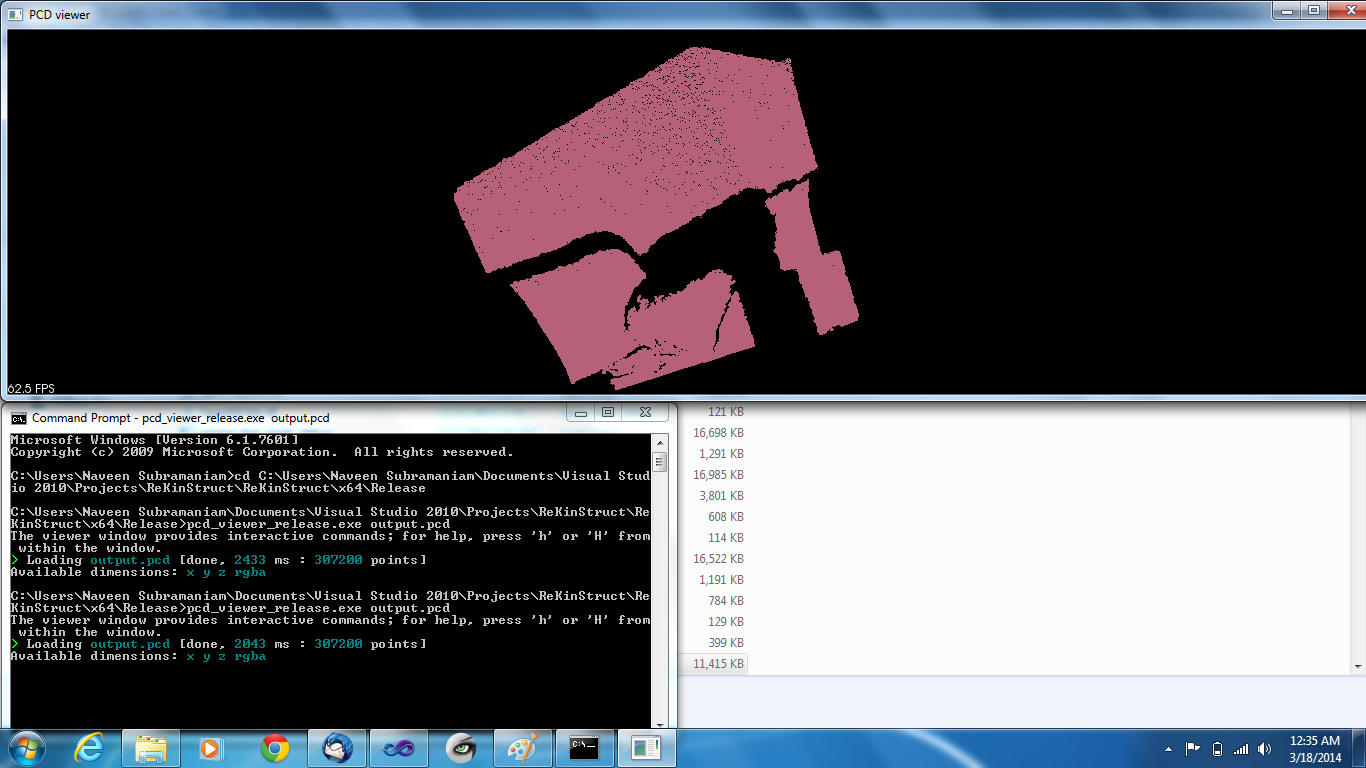
Step 5: PCL program to obtain a PCD

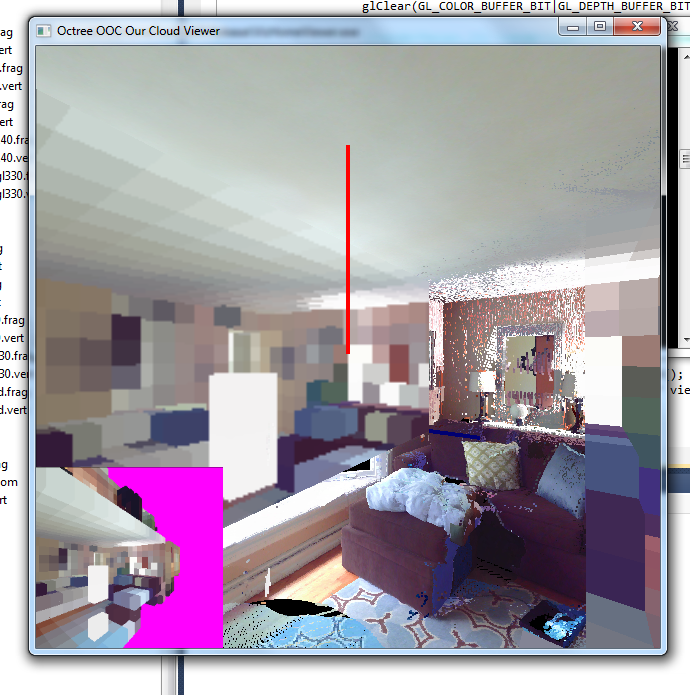
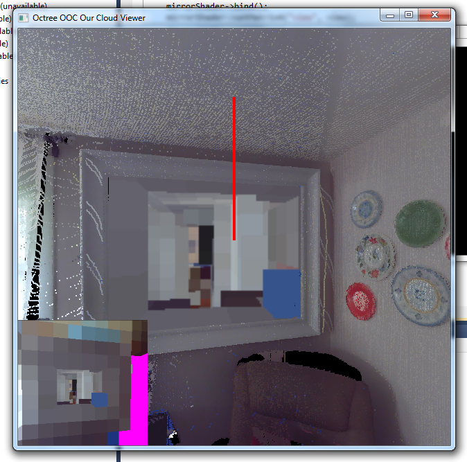
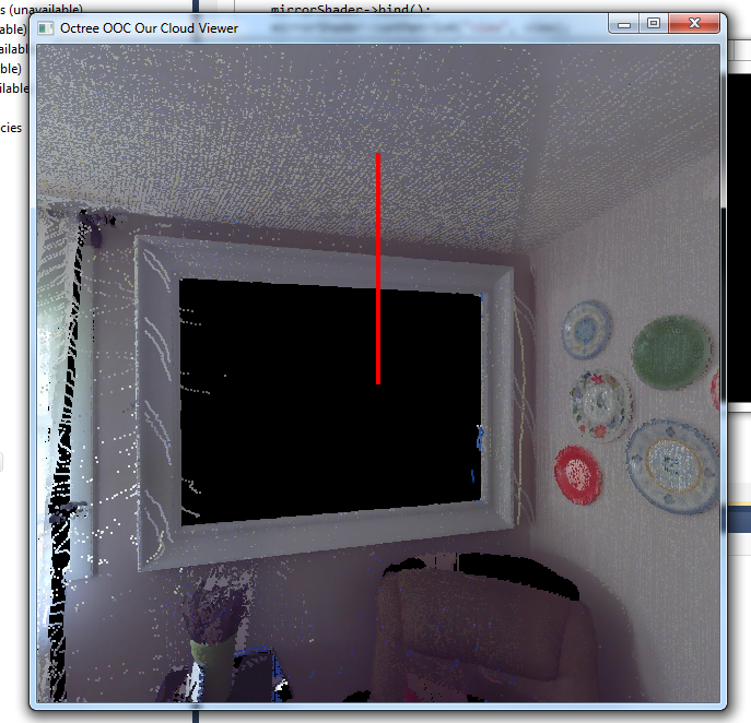
Compile and run the example program from http://pointclouds.org/documentation/tutorials/openni_grabber.php in Visual Studio. Again, make sure the library files and linkers are directed properly in Visual Studio. When the program runs, you must be able to see a visualisation window in which you can see the input data from the Kinect and you can save the frame as a PCD when you click ‘s’.

There you go.!

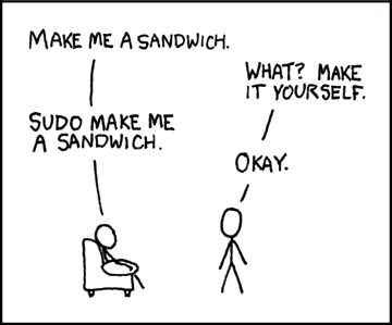
I hope the tutorial was helpful. I know it is not as simple as installing it on Linux or OSX. Reminded me of this meme through out.

sudo sandwich

Image Courtesy: http://imgs.xkcd.com/comics/sandwich.png

However, I hope this post makes it easy now. Have fun. Happy Kinect-ing.!

For further details, email me at nsubramania2@wisc.edu. I will try to help as much as I can.

LEL Project Blog : https://blogs.discovery.wisc.edu/projects/

My Blog : https://blogs.discovery.wisc.edu/projects/author/nsubramaniam/

Week of 3/3/14

(Sorry for the late post – I’ve been having VPN issues with my laptop)

Copper Taffeta:

I finally got a good result on my taffeta etching!  I perfected the salt/vinegar ratio and applied the vaseline more thickly and everything came out great.  Mostly.  While running resistance tests, I wasn’t getting any readings on my multimeter.  I think that the thicker vaseline left a coating on the fabric, which is affecting the conductivity.  I’m working on one more test with thinner vaseline application and a shorter processing time to see if that gets me there.  Next steps: attach an LED and a battery to a fabric “circuit” to see how it functions, then dyeing the polyester backer on the fabric and evaluating if that affects conductivity.

Muscle Wire:

Digging a little deeper into the topic, I’ve found additional levels of complication.  Specifically, in the training of Nitinol wire.  According to many of the sites I’ve been researching, shape training Nitinol requires heating it to 500 degrees and holding it there for 25 minutes.  This sort of heating usually requires a furnace, which I don’t have.  Also, the drawback of this heating method is that it can make the wire brittle and more likely to fail when moving.  Fortunately, I found a teaching guide here which suggests an alternate heating method, via electric current.  I think this is an experiment I’ll be saving for over spring break.

However, the pre-trained Flexinol wire seems much easier to use.  In order to jump right in and make some progress, I’m going to use a tutorial from MIT’s High-Low Tech lab to create a flapping paper crane:

5884436523_1747d41803It’s a nice small-scale project that will allow me to get a feel for how the Flexinol functions on a substrate (paper) that is similar to fabric.  Now I just need to learn how to fold a paper crane!