Our project on 3D motion capture was certainly a learning experience. Although we have yet to make models of phenomena over time, we have certainly improved on our skills in data collection (photographic techniques), post-processing, and model construction and refinement in Agisoft Photoscan.
Data Collection
Initially, we took photos of objects indoors lit by a halogen light, using a 30-110 mm lens. As a result, we struggled with a few issues:
- Due to the directional light, it created diffuse shadows over the model, which made it difficult for Photoscan to align the camera angles. In addition, the hue of the light altered the appearance of the final generated textures for the object (everything was tinted yellow).
- We were attempting to model white-ish objects on a white counter top, which also made it difficult to align camera angles. With lack of apparent textures and similarities in color, it made it more difficult to distinguish between the model and the environment.
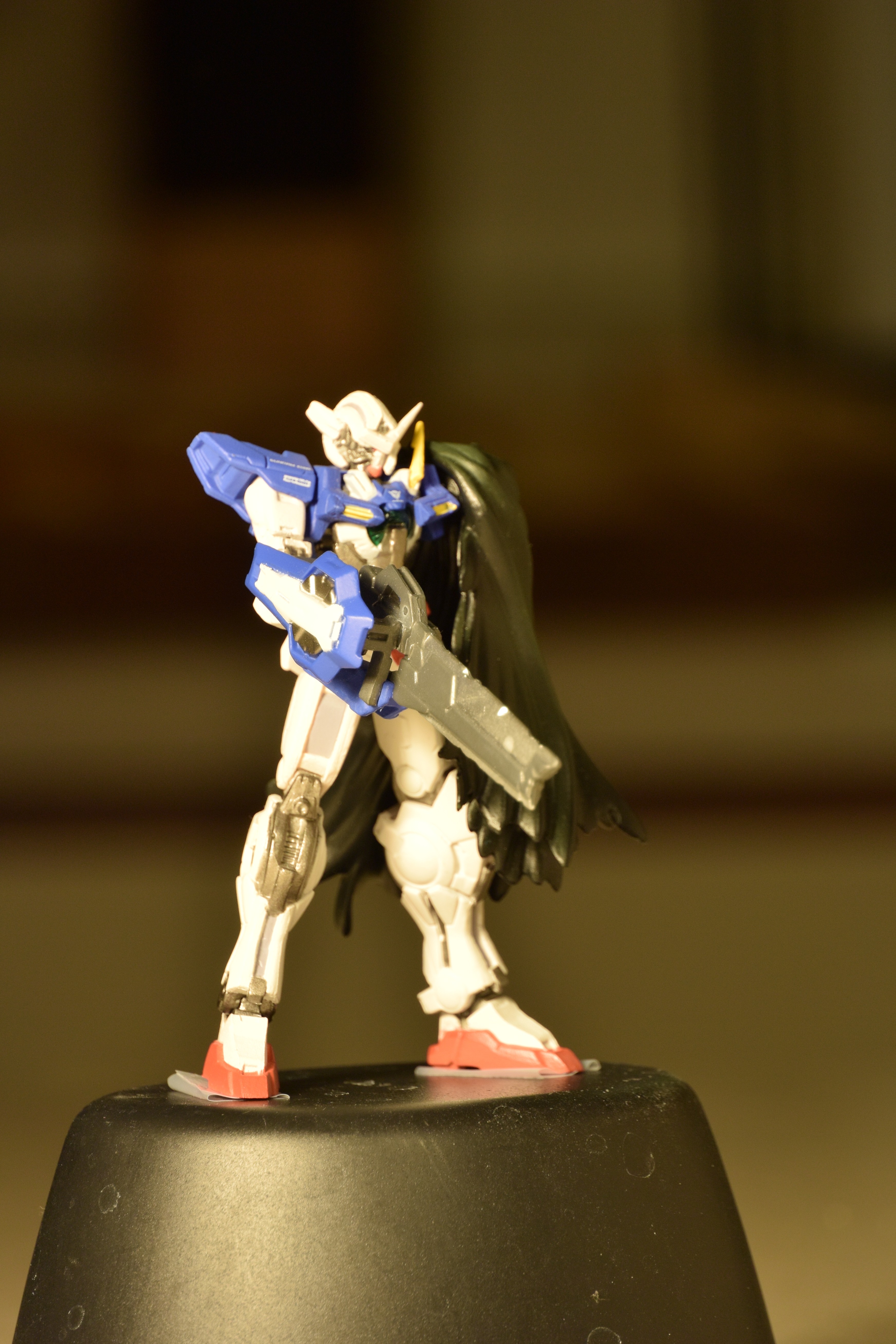
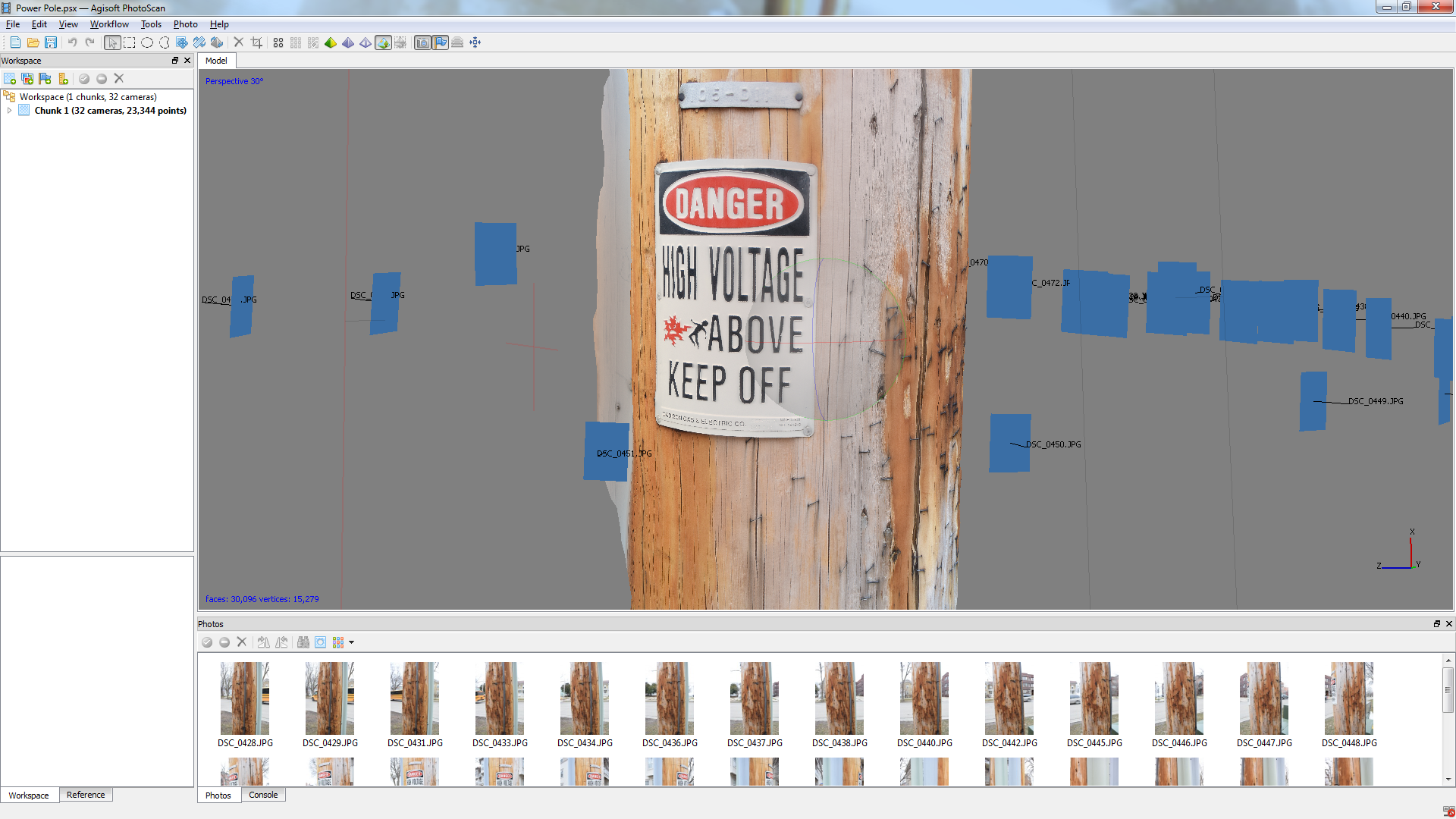
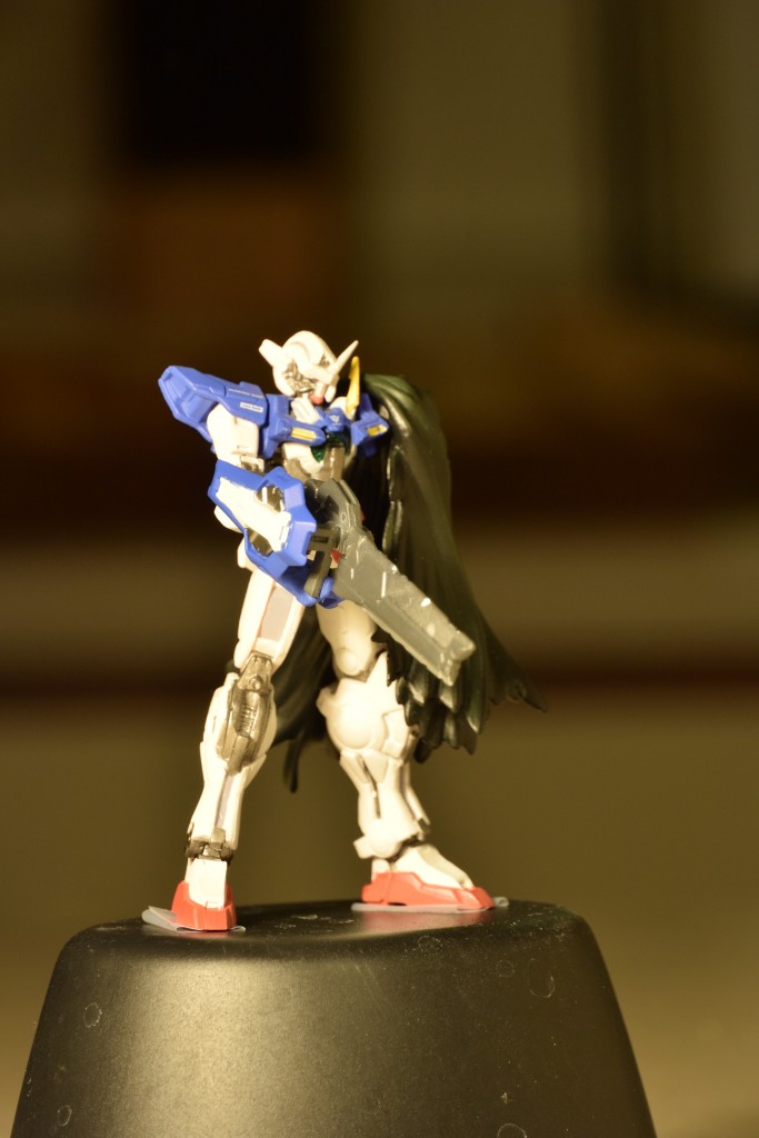
- With a 30-110mm lens, we zoomed in close to the object so that it took up the entire frame of the image, but due to our placement of the camera this created a very narrow depth of field. As a result, if we focused on one piece of the object, other parts of the object would appear blurry, and would interfere both with dense point cloud generation and texture generation. (In the Depth of Field and Color Issues link, you can see how the sword and arm are in focus, but more distant features like the head are out of focus)
- The importance of proper coverage is still something we’re working with. We’ve often forgotten to take high shots of the top of an object to be left with an excellent looking model with a hole in the top of the mesh which can be quite frustrating. This is also true of gaps in the model, such as bent arms or areas between the legs, coverage of these areas is essential to prevent holes or conjoined parts of the model.
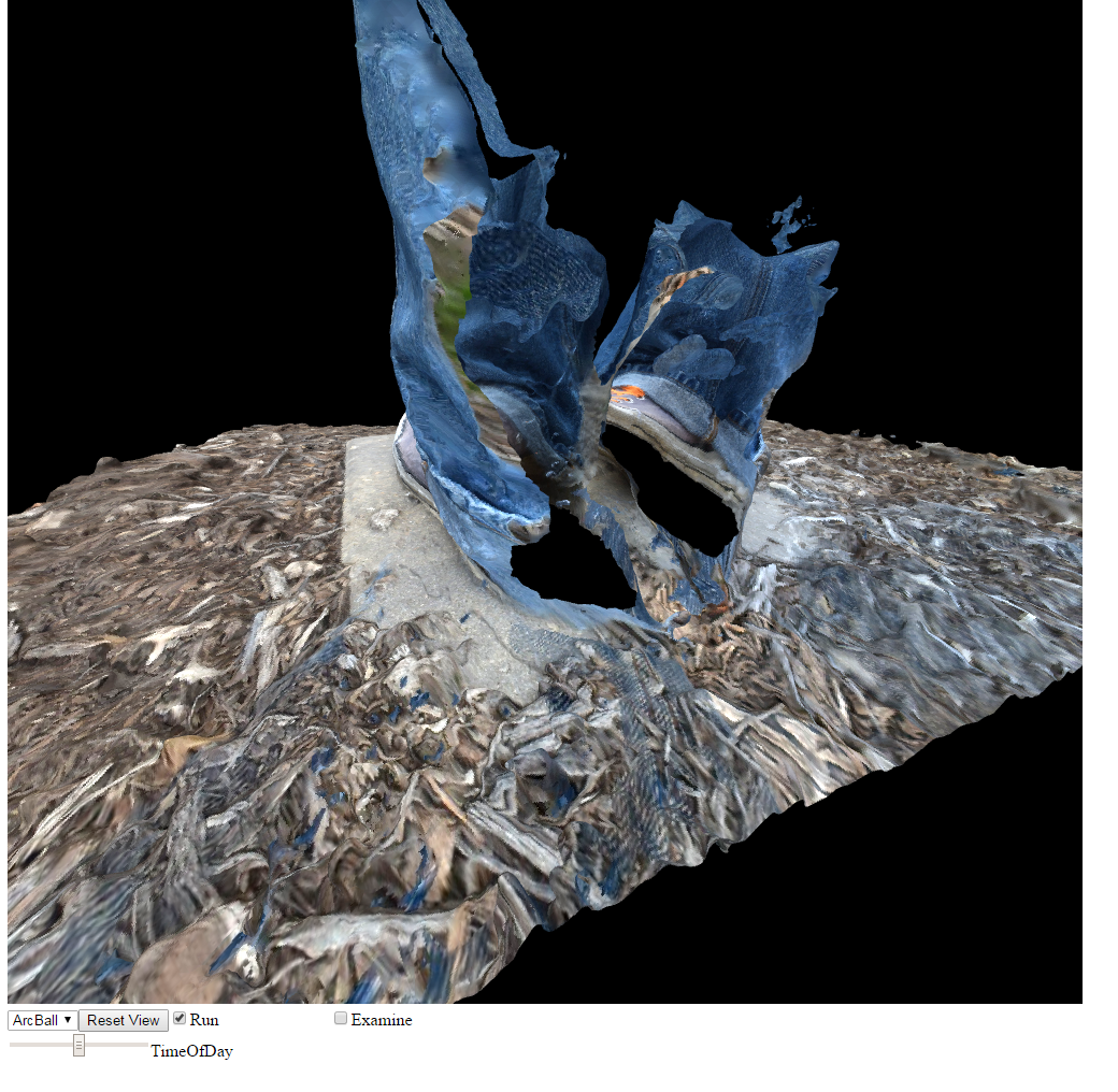
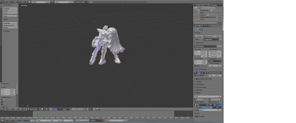
Essentially, with only few images taken in this fashion it would result in models that we’ve dubbed “pudding monsters” due to the lack of well-defined edges and features.

Eventually, we’ve found out that shooting outdoors in overcast conditions provide excellent lighting, as there is uniform lighting all around the object to prevent diffuse shadows on the object. This, in conjunction with more apparent surface detail, allowed for much better alignment and mesh generation. We also found that taking close up shots after getting general coverage really improved the quality of the mesh and texture; it seems that one can mix different kinds of shooting eg. panning and circling as long as there is sufficient overlap between images to obtain alignment. On the note of alignment, we really should be using markers. They speed up the alignment processes immensely and they also help alignment where there is ambiguous overlap. We had to experiment with manually inserting markers into the datasets to get cameras to align in some cases, and while we were able to obtain full camera alignment using this method, it was very time consuming and not something that is viable for constant use. Some object have very difficult times aligning and I’ve had issues getting bushes and large trees to align properly, sometimes only aligning 4-6 cameras out of a 200+ image set. Again, printing out markers could help immensely with this.

Post-Processing
Our final improvements to the project this semester were in editing photos before importing them into Photoscan. Initially, we did no photo manipulation, but later we found that we could perform preprocessing on the photos to correct contrast, lighting, and exposure of the original images. We used this approach on the Mother Nature model from Epic (not shown here) that was shot indoors in directional light. The corrections may have helped with alignment accuracy and depth calculation, but the resulting textures were non uniform due to corrections being greater in certain angles than others. Overall the model turned out well, but there are certainly room for improvements. We are currently using the automatic mode on the camera for very quick modeling, but we wonder if it would be better to use manual exposure settings to maintain aperture, ISO, and shutter speed between photos. This manual constancy should allow for very even textures and consistent exposure settings between photos, but this approach would only be viable for diffuse and well lit subjects.
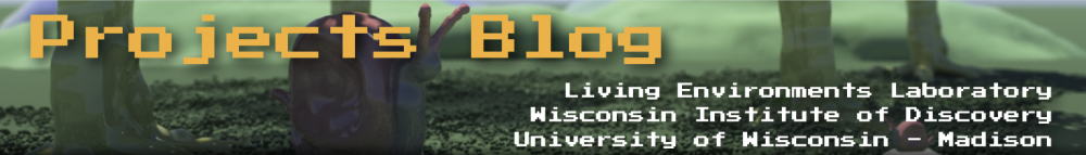
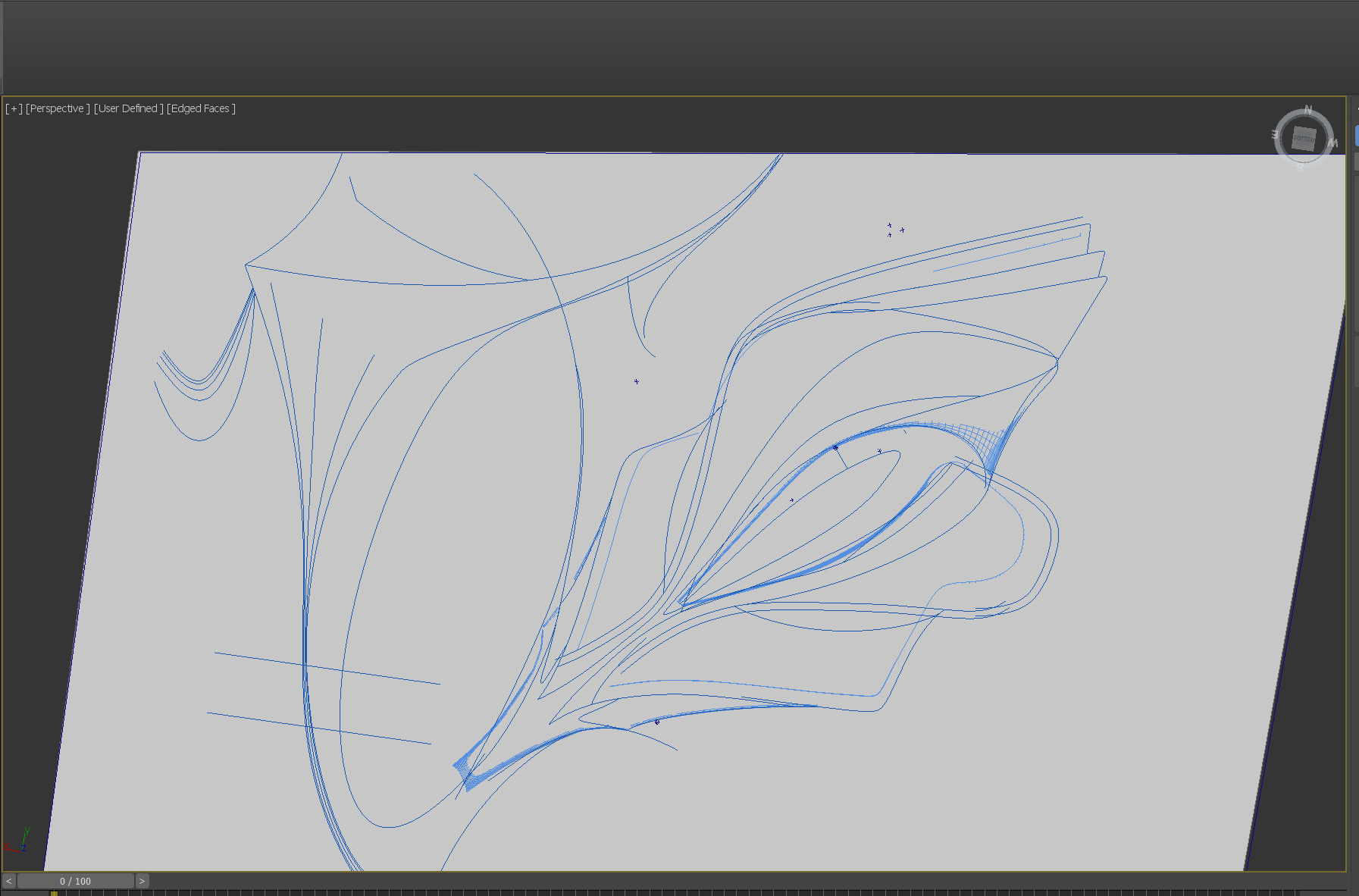
Model Construction and Refinement
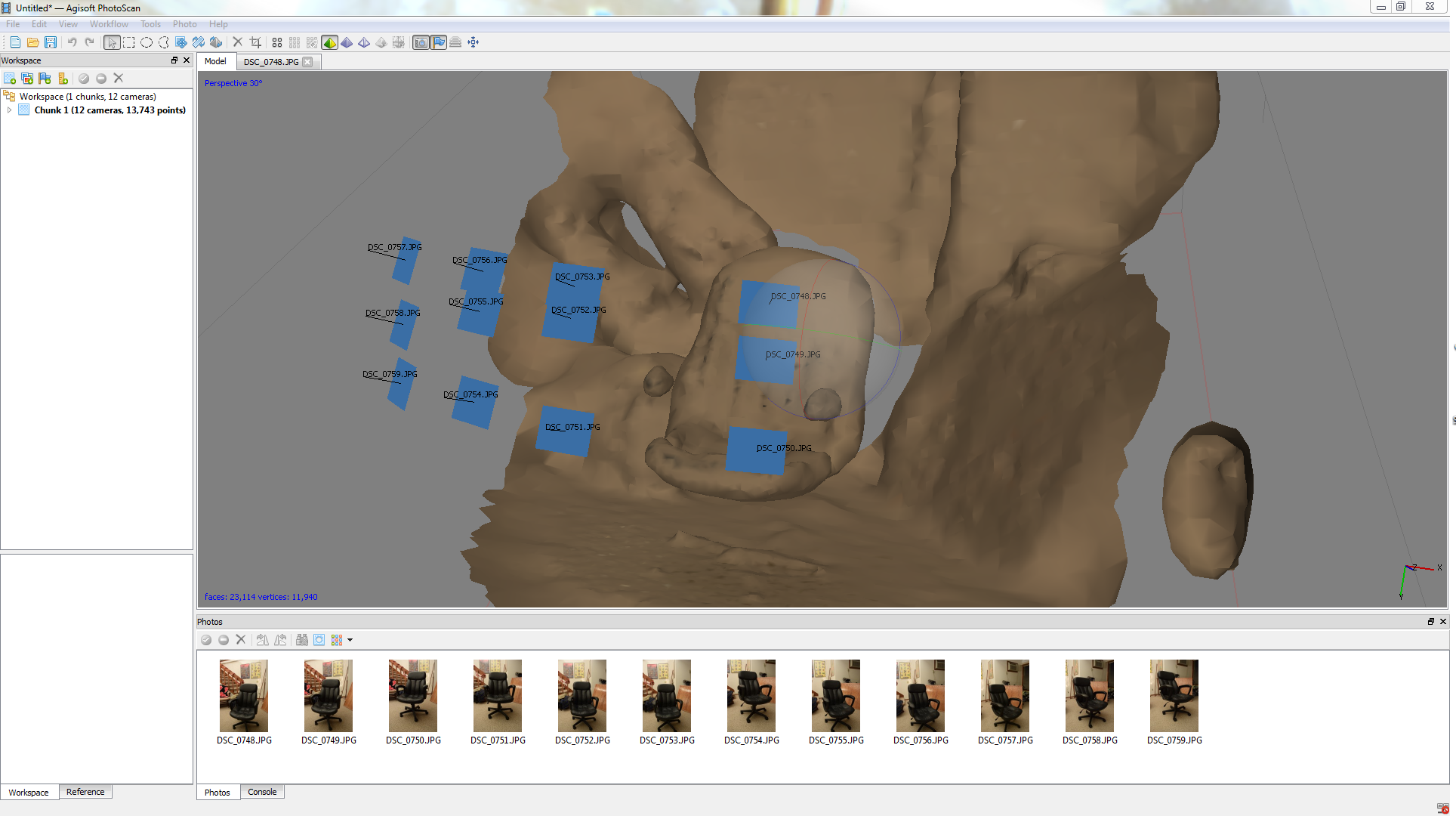
Our biggest mistake we made in earlier stages of the project was constructing meshes from sparse point clouds. Essentially, we were only constructing models by limited datapoints provided when camera angles are aligned. With dense point cloud generation, Agisoft uses photogrammetry (which Andrew and Bryce should learn about next semester in CS 534 – Digital Photo Computation) to construct data points of key features and interpolate values between them, creating a much more detailed data set. As a result, our models turned out much better, even with low-detailed dense point cloud generation.
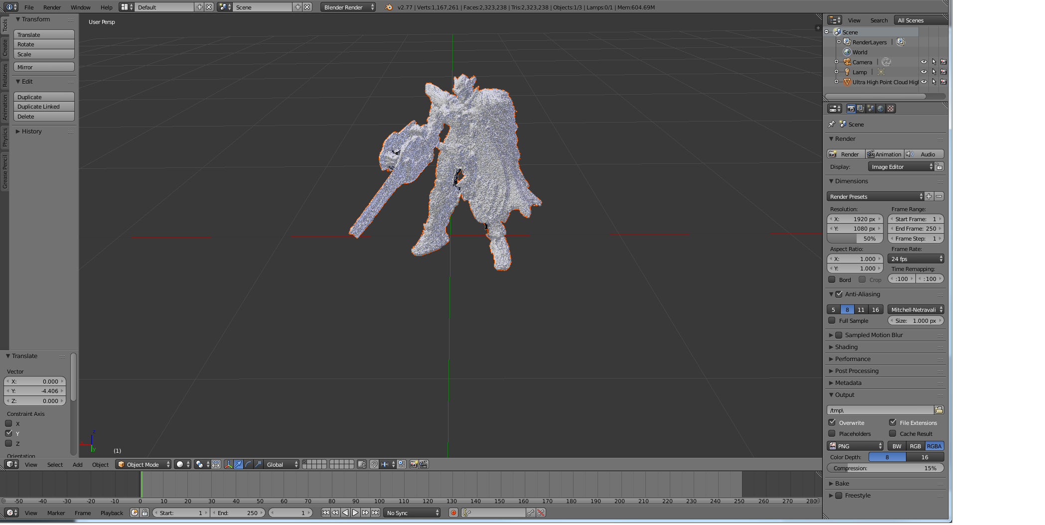
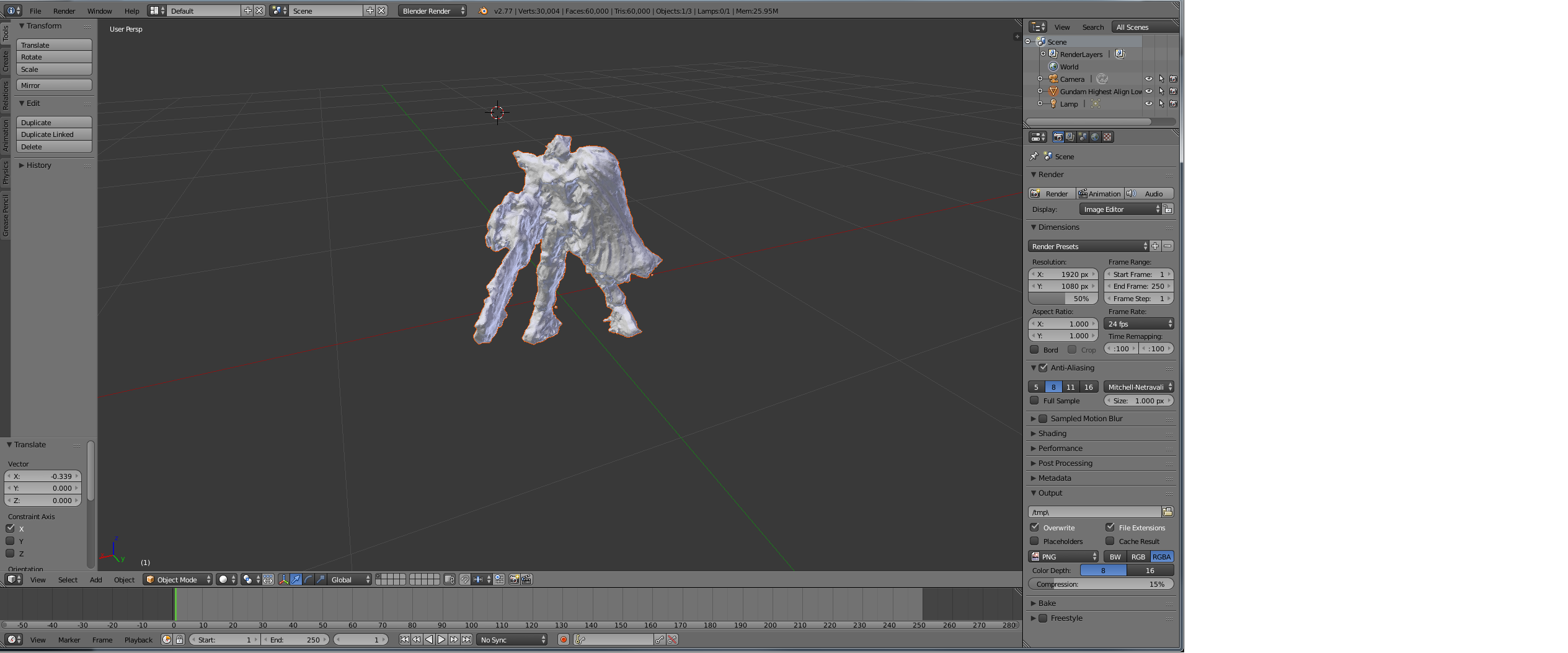
For example, we were able to achieve good results with our Gundam model after manual camera alignment (due to lack of use of tracking markers) and ultra high dense point cloud rendering. However, this was very time consuming and the end model lacked the fine surface detail of the source and the surfaces tended to be very pitted with few smooth planes. We think that this was due to our use of a very shallow depth of field. Our thoughts are Photoscan found the corresponding points in the two images, but in one it was in focus and in the other out of focus, this problem compounded from many angles would likely create a model that has a mix between these two and thus perhaps errors in the depth calculations. In the future we would like to repeat this with a very wide depth of field maintaining focus on all the parts of the model and we expect superior results.

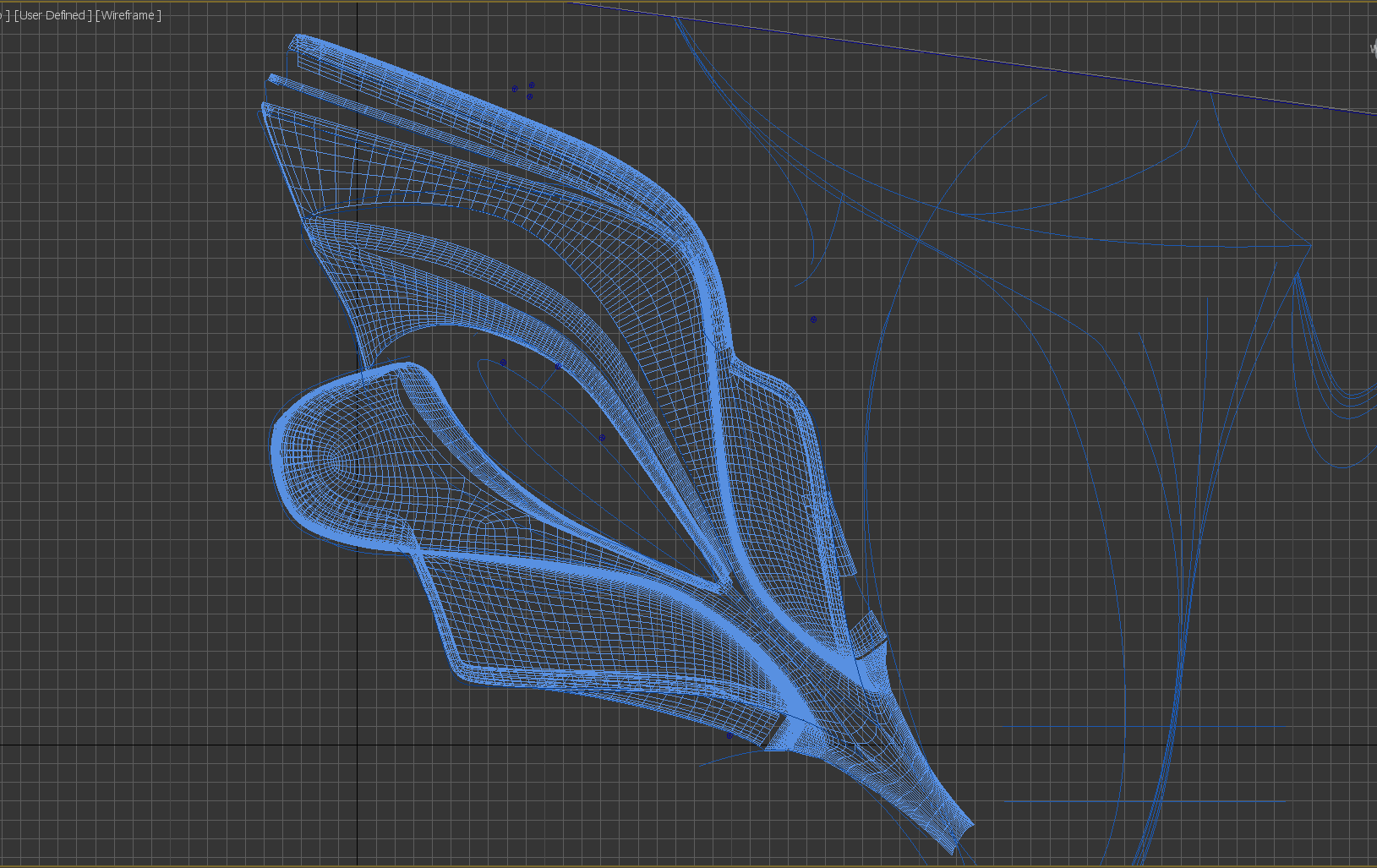
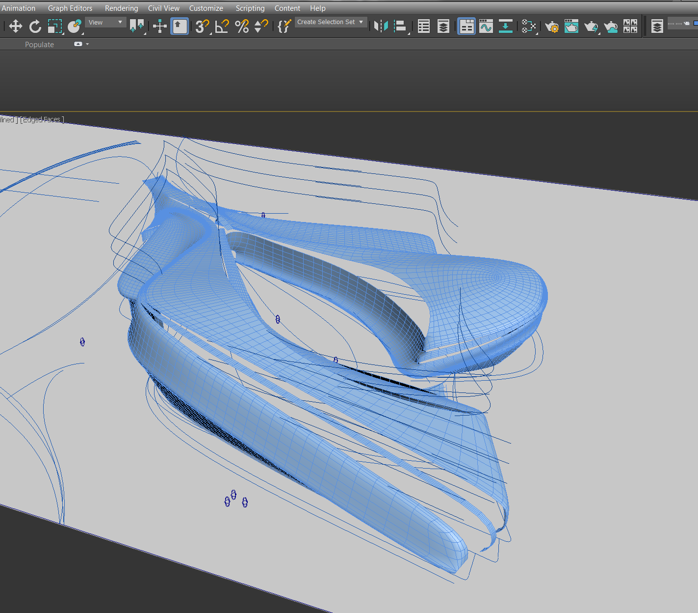
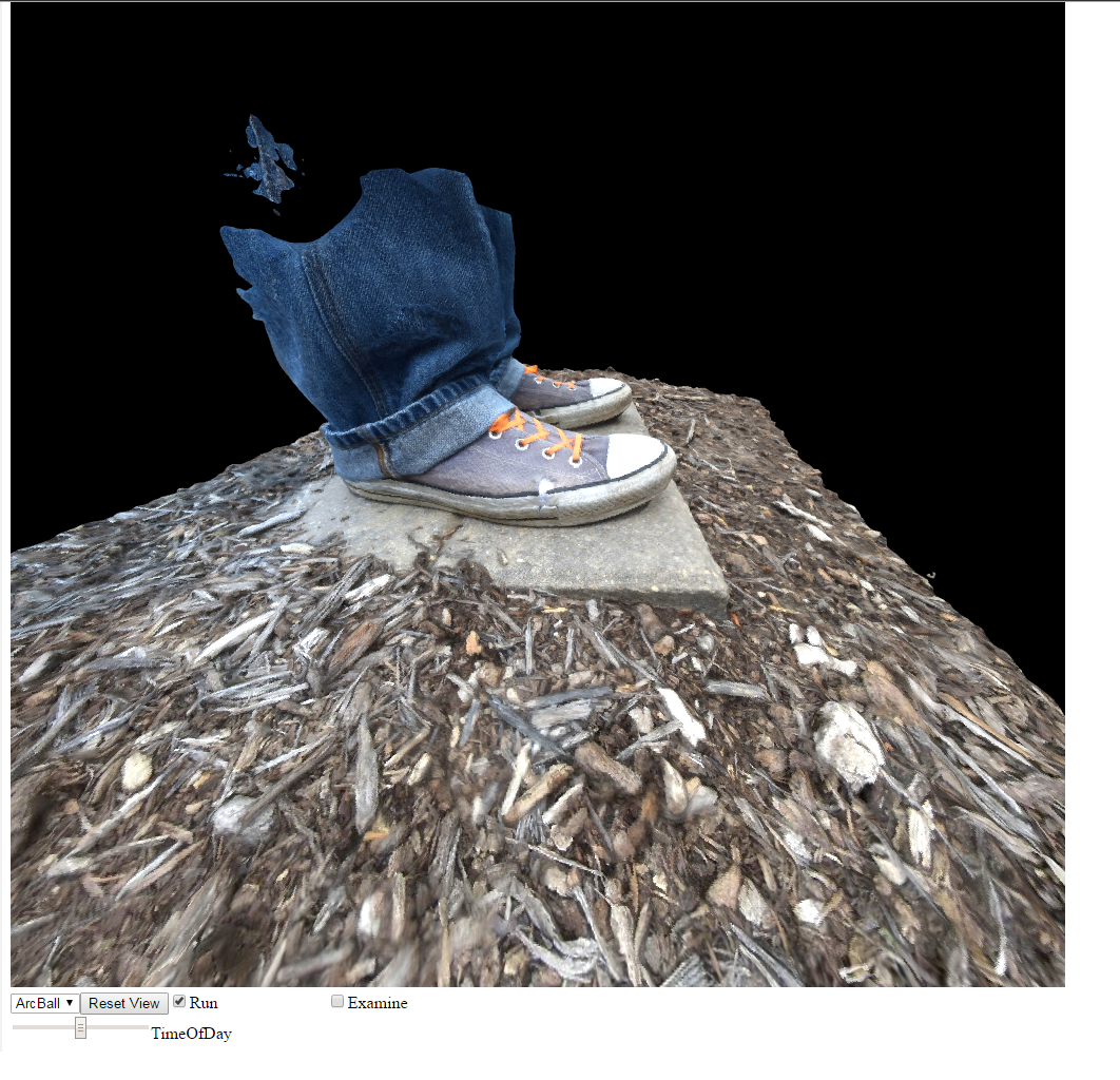
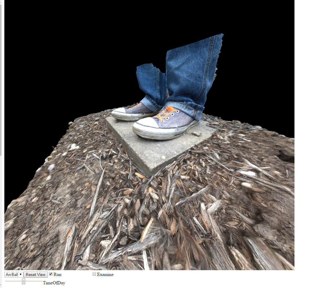
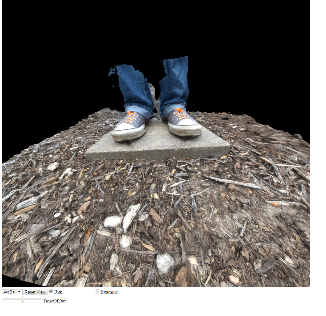
In addition, we refined the point clouds by manually trimming outlying data points, which created a much more accurate mesh. This, accompanied with all prior techniques, allowed us to create a very nice model quite easily:


Here the models are exported from Photoscan as .obj files, and are processed into Javascript files and viewed with WebGL. This just provided an alternative way to view models outside of Photoscan. (We are unsure how to embed HTML files with external Javascript files into WordPress, so that we could view the model from all angles instead of images).
In Conclusion
We’ve had our share of issues, and for the most part, have worked through them. We feel confident in the ability to get decent models, and are looking forward to more experimentation with DoF, markers, and using multiple chunks to obtain high quality on small detailed areas of models, which we will investigate this summer and possibly next fall. We also plan to make models of more imposing objects, such as really small/large structures, and possibly begin looking into making models of dynamic events (starting simple, of course).
We also have ideas of finding “uses” for the models, such as importing them into a game engine or 3D printing them, but we’ll have to see where it goes!
-Andrew and Bryce