Normal Estimation and Point Splatting

This week was spent on getting the point splatting to work in our OOCViewer.

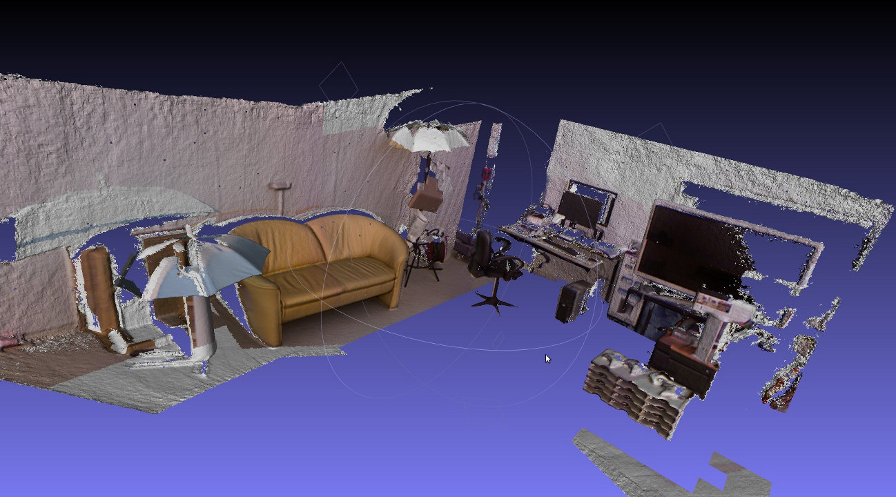
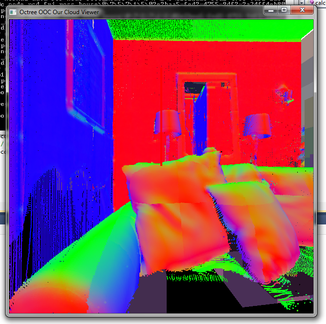
Right now, normals are calculated for each voxel independently. This can either be done during runtime or in a pre-processing step. In the first case, normals are cached on the disk after calculation and can be re-used. This also has the advantage that ‘mixed’ scenes are possible in which some voxels have normals but others dont:

Online calculation of normals

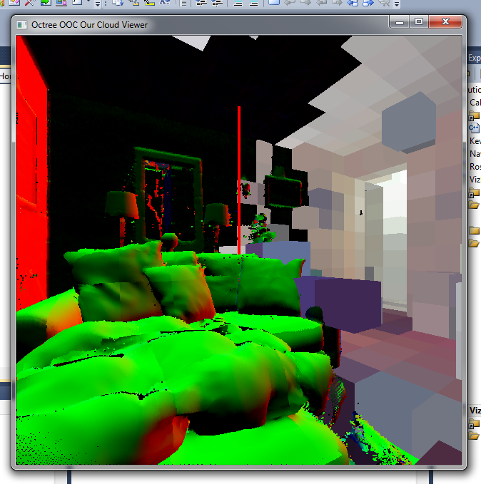
Online calculation of normals. Some voxels have normal data, others don’t. The voxels in the background right have not been loaded yet.

Calculation time depends mostly on the number of points in a voxel. pcl’s estimateNormals method turned out to be faster (especially when using the multi-threaded OMP variant) than the naive normal estimation approach and was used. In a second pass, a K-nearest neighbour search is performed for each point in the point cloud and the average distance to these neighbour points is used as a starting radius for the splat size.

The drawbacks are increased memory size. On average each pcd file now has an accompanying normal cache file that is 1.5 the size. Normal data is currently not compressed. Another option would be to store normal+radius data as 4 signed chars (32 bit total) and normalize the value in the shaders.

Pre-calc time is pretty high as there are many small files and a lot of time is spent onopening and closing files. On the other hand, this has to be performed only once.

There are some sampling problems with the normals like in this image:

Normal discontinuities

As a side note: merging two branches is harder than it should be. Maybe we could organize the git branches a bit better?

IPD Fix. Starting stylus integration.

The issue that I was having last week with two images appearing was fixed today. The solution to this problem was to make the inter-Pupillary Distance (IPD) smaller. The IPD is the distance between the two pupils of the viewers eyes. By making this value smaller, it made the two images that are rendered in the world builder application appear closer together. Below is an image demonstrating this.

At first I thought this could be a problem with the Nvidia Quadro drivers, and luckily it wasn’t. The next step is to get the Stylus operating within the world builder application. The plan is to spoof the current code for the joystick and use it with the stylus. After this is complete I believe it would be beneficial to get the world builder application to run with out the skeletal viewer. Doing this would decrease start up time and will improve the speed of the world builder when using the leap motion.


UPDATE:
Stylus is now being detect in the world builder application. Next step is to add some type of beem or cursor to the stylus. After this is accomplished I can map the key bindings so that you can select and rotate an object in the world builder app.

Not as easy as it looks…

…has been my on-going experience with the copper taffeta experiments.  My second attempts didn’t even make a dent in the taffeta fabric for the first day or so.  I left it in the bath (because, why not) and when I checked it again several days later the copper had etched away – including the portions covered by Vaseline!  I think that screen printing creates a film of Vaseline that is too thin to adequately resist.  I’m thinking that stencils will be a better choice going forward, with the possibility of laser cutting them once the forms become more complex.  I started a third vinegar bath last night with a thicker Vaseline layer and am hopeful I’ll get a cleaner outcome.

I did a little testing with my multimeter on my original sample.  As expected, my readings were all over the board.  I think the key will be to get a crisp separation between copper coated areas and base polyester areas.  In my research I stumbled across a diagram of the Lilypad PCB:

This would theoretically allow me to build an Arduino into the actual fabric of a project.  Finds like this make me even more determined to work out the bugs on the copper taffeta process.

I also received several samples of muscle wire from SparkFun, both Nitinol and Flexinol.  I’ve been doing some research on the specifics of working with these materials.  Since I have 4 different samples, I’m going to try 2 variations in each wire type – one set up utilizing the natural contraction of the wire and another where I “train” the wire to a shape.  I’m using this article by Jie Qi as a jumping off point.  The first steps will be purchasing crimp beads to facilitate attachments and an appropriate power source.  It sounds like if any of my experiments are going to end in fire, it’s this one!

Tiling and Hosting and Post-Its

First tiling of the large image done, just as a test (only used plain outline of onion)

Using the Bramus adaptation of various tiling scripts, this version was written as a Photoshop plug-in so it could be done directly, without exporting. The 32k x 32k image took about 2 hours to finish, much smoother than I expected! (this used my plain onion outline, rather than the cell-version still in progress, to test the simplest line for speed. We’ll see how the added detail changes things…)

As a map it worked! With some slight adjustments to the x-axis parameters, (the image was repeating horizontally).
The trick is getting the images posted online so that it can be shared. Seems quite simple… post the images on the “mywebspace” through UW and tell the code where to access them, put code into WordPress, easy-peasy.

MYWEBSPACE
is a monster.

I can only upload files one by one. I can only upload folders if I use the Java Plug-In, which does not work on Chrome and refuses to allow access through both Safari and Firefox, citing that Blackboard (the underlying system of mywebspace, presumably?) does not have sufficient permissions to run, and it errors out, giving this text file when I ask for more details, which only seems to be a list of possible error codes:

Missing required Permissions Manifest Attribute in Main Jar

Missing Application-Name manifest attribute for: https://mywebspace.wisc.edu/xythoswfs/lib/XythosUpload.jar
Java Plug-in 10.51.2.13
Using JRE version 1.7.0_51-b13 Java HotSpot(TM) 64-Bit Server VM
User home directory = /Users/JackiW
—————————————————-
c:   clear console window
f:   finalize objects on finalization queue
g:   garbage collect
h:   display this help message
l:   dump classloader list
m:   print memory usage
o:   trigger logging
q:   hide console
r:   reload policy configuration
s:   dump system and deployment properties
t:   dump thread list
v:   dump thread stack
x:   clear classloader cache
0-5: set trace level to <n>
—————————————————-

I naively tried just dropping the folder of images into my list of folders to get around the problem, but that is just an obtusely simple solution. Mywebspace 1 GB of space, which is enough for the moment, and I’m sure I can request more as it is needed. The uploading issue is something a little bigger. I will try contacting DoIT to see if they have alternative suggestions for navigating this.

I will also have more time to look at this tonight, and most likely will host my images through my work website if I can’t get this sorted. Uploading these one by one would be like wallpapering your house with post-its.

(…. that might actually look pretty interesting, especially with a slight breeze…)

Below: a bit of the level 3 zoom magnification of a (very rough) line drawing of an onion. Each tile 256 x 256.

3_3_0

3_3_1

3_3_2

3_3_3

3_3_4

3_3_5

3_3_6

3_3_7

ReKinStruct : The Hardware-Software Battle

So, I was trying to obtain PCDs from the Kinect and in order to do so, I wanted to read something from the Kinect. Like I mentioned in the previous post, I had PCL and MSVC2010 installed. I had also obtained the latest version of OpenNI and SensorKinect to serve as drivers for the Kinect. And the following happened.

I had one line of code that initialises the Kinect and returns a pointer to grab data. It kept crashing at run-time and there was no stack trace. A little bit of googling led me to believe that OpenNI does not comply with my laptop’s underlying hardware.

Okay, *deep breaths* that is not a dead-end. There had to be something else. So I got Kinect Fusion installed from Microsoft site. And from the tutorials, all I needed to do was type one command line code and my Kinect would (magically?) start obtaining a PCD. Although what happened was a different story.

There was something wrong with my Graphics card. I tried installing the latest CUDA drivers from NVIDIA but that did not help too. I have an Intel 4000HD Graphics card on my laptop and I wonder if KinFu works only with NVIDIA Graphics cards which would mean I would have to start using another machine.

So, the plan for this week is to check if the Kinect works on another machine and start proceeding from there. I also have a bad ( and a good ) feeling that I might have missed installing something on my laptop and so I can get the Kinect working on my machine too. Will keep you posted.

All in all, the classic conclusion, Hardware and Software do not like each other.

ReKinStruct – PCL : Check

So, the aim was to get PCDs from Kinect as soon as possible so I can start working with the point cloud data. On the way, I stumbled into getting the hang of how Kinect works, some basic programs that came along with the Kinect like obtaining a color+depth image, skeletal viewer etc.

Apologies if it looks distorted, had to both be in the image and take a screenshot (And taking a screenshot on Windows with a Mac keyboard requires clicking keys on all corners).

There were few more installations before even getting the Kinect running. Point Cloud Library with its 3rd party dependencies and OpenNI framework are installed and running. Compiled a simple program that reads data from Kinect and displays it on the screen. Stumbling into runtime errors and code halts. Memory usage is already up to 3GB which is three-fourths of the total. Let’s hope it doesn’t crash any soon.

Essentially, would like to get something like this in the next few weeks.

Image Courtesy: pointclouds.org

The target for this week is to get the program working on the IDE and start reading some data from the Kinect and store them as PCDs.

3D Space Exploration

This week I read through the documentation and got acquainted with both the Leap Motion  and the ZSpace SDK’s.

An obstacle in this project is that the leap motion is very particular in the way you place your hand over the device. It almost always needs to be perfect in order for the leap motion to detect the hands correctly. (I will post screen shots tomorrow). Also, when you use the ZSpace with the world builder application, you will see two images on the screen while the glass are on, if you close one eye, or take off the glasses, you will only see 1 image.

Ross was able to help me get the leap motion to recognize and display hands is the world builder application. This is a great stepping stone to my the final piece of my project. I first want to get the stylus from the ZSpace to work in the world builder application, there is great documentation in the ZSpace SDK for this.

Goals this week:

1) Get stereo image working, currently showing two images unless glasses are off/glasses are on with one eye closed. **fixed** A simple restart of the computer fixed this issue, surprisingly enough. Next I will try to add an object to the world builder application and see if the 3d effect is working.

2) The world builder application runs smoothly when the skeletal viewer is not selected. But in order for world builder to recognize the leap motion, the skeletal viewer needs to be selected and this causes the application to run very slowly. For this goal, I would like to flag the skeletal viewer to show leap motion data with out the skeletal viewer showing. This will greatly improve the performance of the application.

3) Get the Stylus to work in the world builder application.

So as of right now I am seeing both the right and left images. They are not converging in the world builder application. This obviously doesnt give the immersive effect of being able to rotate the head and see around the object. So in order to move forward, this will need to be fixed.

The figure above demonstrates how objects are seen on the ZSpace screen.

This is what an object looks like with the glasses on. This picture was taken with the glasses off but the two objects are similar when the glasses are on/off.

Acid etching copper taffeta

My first round of testing was etching conductive fabric to create circuits.  I’m working with a sample of copper-coated taffeta from LessEMF.

Working off of this tutorial, I began by screen printing a design onto my taffeta with a resist, in this case Vaseline.  I then soaked the taffeta in a vinegar & salt solution, which should etch away the unprotected copper coating, leaving behind the polyester fabric.  The tutorial suggested a minimum etching time of 12 hours, however there was no effect in that time so I left the taffeta in the etching solution for several days.

Here is my initial outcome:

As you can see, while the fabric is etched, the outcome is less than perfect. There are a few variables I am refining for my next test:

1. Solution mix – While the tutorial calls for a ratio of 100ml vinegar to 7ml salt, I transposed things in my mind and tried to mix a solution of 100ml vinegar to 70ml salt.  Once I realized my error, I removed some of the excess salt.  However, I am uncertain what the makeup of my final solution was.

2. Salt type – For the initial experiment, I used pickling salt because it was what I had on hand.  For the next round I will be using standard iodized salt, in case the iodine content  factors into the etch.

3. Container – The first test was executed in a basic Tupperware bowl, which I quickly realized is not the ideal container given the delicate nature of the Vaseline resist.  Subsequent experiments will be conducted in a shallow pan.

4. Resist thickness – It may be beneficial to apply the Vaseline more liberally when printing, in order to better protect the copper from the etching solution.

Next steps:

I am going to put together a second round test, applying what I have learned from the initial experiment.  Once I get a clean etch, I am going to experiment with a few different dye formulations to see if it is possible to color the white taffeta without affecting the conductivity of the copper plating.  Also, I’d like to use a multimeter to test the conductivity across my etched design to start getting an idea of any potential size limitations.

Maps and Tiles

The files for the project are quite large, it takes about 5 minutes to save the largest files. (I know, I know, of course a 32k x 32k image is going to take a long time, what did you expect? Well, I expect my computer to be magical, that’s all. The images for various zoom stages are composed separately (using the same outline as the basis to maintain consistency) and I will be substituting more detailed renderings as needed for the appropriate levels of magnification. I had them grouped as layers for a very short period of time, until it was clear that additional layers seemed to exponentially increase the time required to save my file. This may seem like child’s play to an experienced programer, but I am enjoying learning about it.

In order to be most compatible with the google API, the images are made with these particular pixel dimensions:

256 x 256 ——— 1x magnification
512 x 512 ——— 2x
1024 x 1024 —— 4x
2048 x 2048 —— 8x
4096 x 4096 —— 16x
8192 x 8192 —— 32x (slightly smaller than the 40x equivalent magnification
16,384 x 16,384 — 64x
32,768 x 32,768 — 128x (slightly larger than the 100x equivalent magnification)

I do realize these won’t be precisely accurate, since the first onion image is not exactly at life size – but the 1024 size gets closer to the actual size so I am rounding the estimated measurements up one degree (so the 16,384 is closer to the “40x equivalent”, and the 32k image will be rendered slightly smaller than “100x equivalent”). This should not be an issue for the cricket and for the Paramecium, since the 256 x 256 should be more than enough space for “life size” (a single slide, in the case of the unicellular organism). For larger life forms in the future, these measurements will be adjusted accordingly.

Prof. Kevin Ponto found software for splitting images into ready-made tiles for use in Google Maps API formats: Maptiler Free online, which promises incredibly quick working time: (2 minutes as opposed to 122 minutes, and half the finished file size). This program has very good prospects but is limited to 10,000 px images and it leaves a watermark on the image that is tiled. I will try this one to see how it compares to another free version from Mike Courturier: Tile Generator – test map loading this weekend, hopefully.

Maptiler Start: The next level (costs ~$28 USD, not bad) does not put a watermark on, but it is still limited to 10k pixels and requires(maybe?) 2 CPU cores. That end size will bring us to approximately 40x zoom, which equates to the lowest lens on a standard compound microscope. I have been developing the drawings at 32,768px, which gets me slightly above 100x magnification, which would be ideal. The highest level of magnification would be 400x magnification, but that may be reserved for the Paramecium… (which I probably should have started with, being a single-celled organism…)

Maptiler Pro: The next (and most expensive level at ~$560 USD) offers unlimited size, so I could get the zoom I want, but in addition to the hefty price tag it requires (maybe?) 4 CPU processors.

I think I’m willing to wait a few hours for images to tile. We’ll see though, perhaps a step up would be worth it.

Also posted on jwhisenant.wordpress.com

Conversations and Reference Sources

I have had several helpful conversations over the past week, and there have been many good thoughts and suggestions regarding this project.

Kandis Elliot – Scientific Illustrator: Botany Dept./Zoology Dept. 
Kandis had lots of advice and was very generous about sharing her process when approaching scientific illustration – after meeting with her I immediately went and made a reference sheet for Photoshop keyboard shortcuts (I knew the basics, but when you are able to fly through the toolset, it cuts your work time down significantly). We talked about information design, image rendering, and dinosaurs!

Sarah Friedrich – Scientific Illustrator and Media Specialist: Botany Dept.
It was very fun to speak with Sarah (after I went to the correct floor…) It is incredibly helpful to explain the scope of a project to different people, even just to articulate my own thought process out loud, as well as hearing alternate perspectives. We talked about layers of design (especially for organisms with multiple systems to represent: digestive/nervous/endocrine/etc) and were tossing around ideas of how that might be approached as a layering process to integrate the system representation, or if they would be completely separate.

Mike Clayton – Photographer/Collection Manager: Botany Dept.
An incredible resource for imaging suggestions – and generously offered the use of the Botany Dept compound microscope with a screen viewer, on Fridays. In addition to the comprehensive resources of the UW, he recommended looking for existing slides from Ripon Microslide for any specific botanical material. He has also compiled some fantastic images of plant material using a nice quality flatbed scanner (one of the many helpful tips: for 3D objects that you don’t want smashed against the glass: scan with an open top in a dark room – the resulting images are dramatically lit with a deep black background).

Some images from the UW collections: excellent reference points for 40x versus 100x magnification. Right now the only available slides are of root tips, so I am growing an onion from a common bulb in order to get leaf cell samples… (I had one in the kitchen but my industrious housemate discarded it… oh well) For the actual rendering, I am drawing one root’s worth and use it for the other root tips as well, adjusting for different curves, etc).

Image from UW Botany Department, scanned by Mike Clayton

Onion_UWBotanyDept_AlliumRootMetaphaseSpindle

Marianne Spoon – Chief Communications Officer, Science Writer for the Wisconsin Institute of Discovery
We met to go over the scope and plans for this project. Marianne had some great presentation format suggestions – I had been focusing mainly on the individual images but she was talking about how viewers might encounter the image options on a hypothetical website (i.e. possibly in a compiled image with hotspots on an where people could click on an onion/cricket/etc and then go to the zoomable map view. She was also wondering if the image would go even farther out, zooming out to a room, a building, a country, a planet. Perhaps something to consider in the future – maybe seamlessly link to a separate zoom map, since my files are getting quite large just from a “lifesize” viewpoint! She made me really start thinking about the larger integration of these anatomical maps into their intended application or something that I might not have anticipated!

In other news, I have several reference drawings from our entomology lab cricket dissections last week, so I have started compiling initial sketches of the internal systems for an upcoming map.

(also posted on jwhisenant.wordpress.com)