Started exporting/importing data about mirrors from SCENE into the VizHome viewer. Currently all surfaces with mirrors are manually preprocessed (to get rid of the false mirror points), so adding a few steps to this process seems okay for now.
Right now it works like this: in the scan (2D) view, select a region of the mirror and delete these scan points. Then, redraw this region a bit larger and create a plane. Check in the 3D view that the plane aligns with the wall/mirror. Then, in the 2D view again, create 4-many corner vertices of the mirror using plane/intersection points and save them all in a VRML file.
Now, SCENE is quite inconsistent when it comes to point/model transforms and during export it does not apply the global scanner transform to these points. Additionally, the EulerAngle transformation provided by SCENE does not say which rotation is applied first. Luckily it also stores the rotatation in axis/angle format. When loading the points in VizHome you therefore also have to specify the axis/angle and translation as the global transform for each mirror.
The current mirror file (for Ross’ house) looks something like this:
new_mirror kitchen_mirror
translation 1.268844 2.561399 8.353854
rotation_axis -0 -0.002 1
rotation_angle 138.859284
points 4
-5.09820000 1.16210000 2.61530000
-5.10310000 0.26780000 2.61300000
-4.95730000 0.26350000 1.41670000
-4.95220000 1.17380000 1.41860000
end_mirror
new_mirror bathroom_mirror
translation 0 0 1.066999
rotation_axis -0.003 0.001 -1
rotation_angle 136.756113
points 4
-0.09780000 1.14360000 5.32700000
-0.09620000 0.36530000 5.32200000
0.02890000 0.37050000 4.28740000
0.02730000 1.14700000 4.29170000
end_mirror
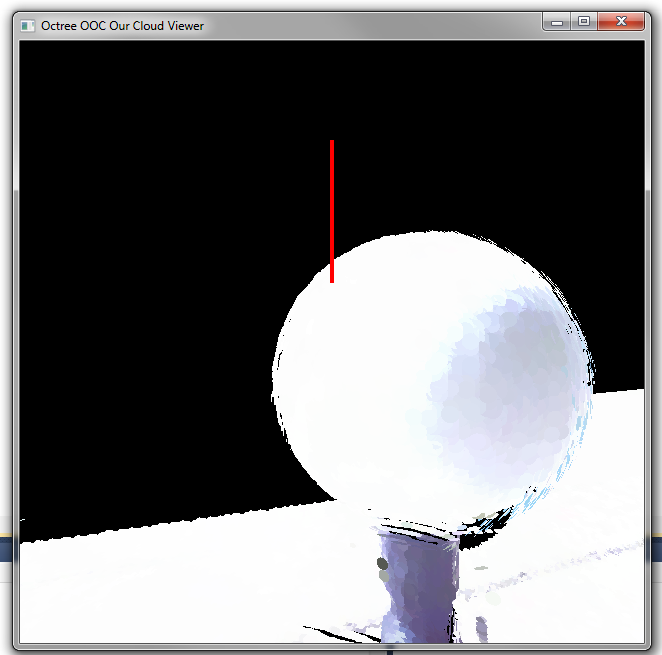
Most entries can be created by copy-pasting and the file supports multiple mirrors. Both mirrors have different transformations as they were marked on different scans. Once loaded, it currently looks like this:
Mirror geometry loaded
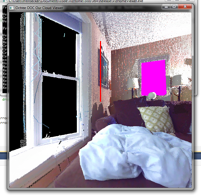
We also now have an (optional) background:
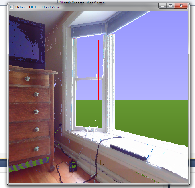
Background rendering
Colors can be changed in the shader. The background is drawn using a single screen-filling quad and determining and interpolating the current view-vector for each vertex.