All posts by sylvestre

My name is Jason Sylvestre and I am currently a freshman studying Electrical Engineering here at UW-Madison.  While in high school, I was very involved in search and rescue robotics research and competed at the Intel Science and Engineering Fair where I received a third place medal out of nearly 1800 students from over 70 different countries.  This passion I developed for circuitry and EE brought me to the Living Environments Laboratory where I will be working under the supervision of Professor Kevin Ponto to build a thermoelectric bracelet that can be used for personal thermal comfort.

TEB Final Post


Final image

TEB Poster

Description of project?

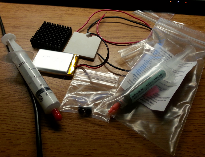
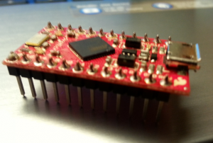
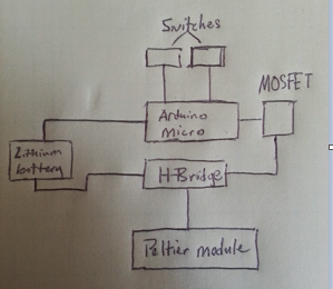
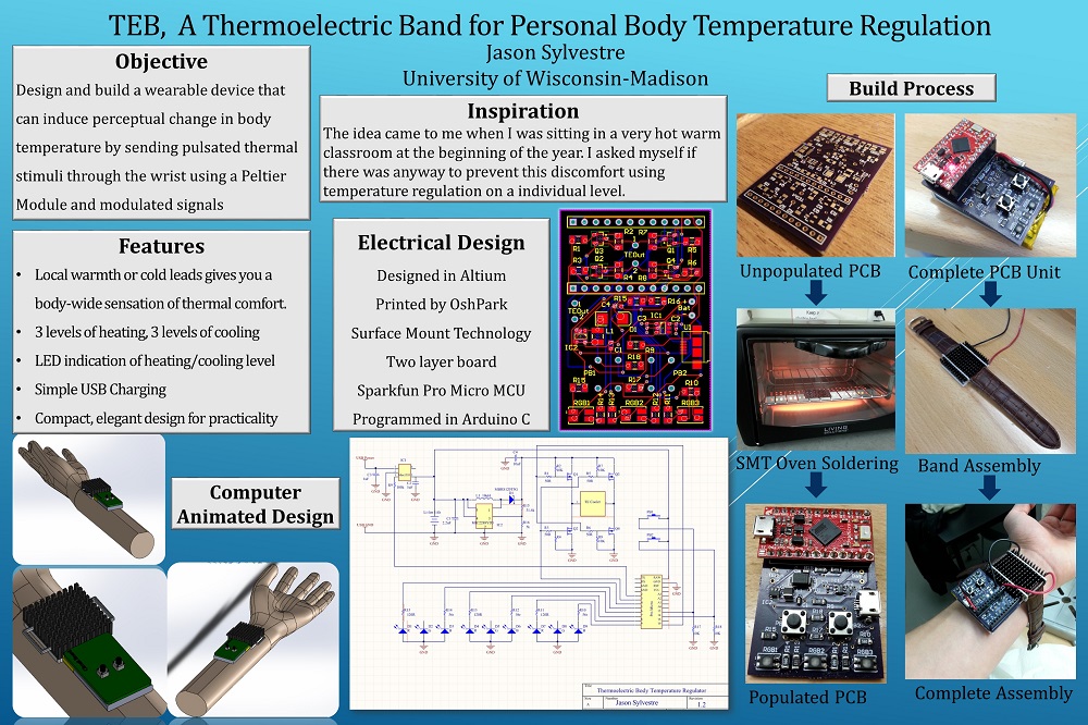
TEB is a thermoelectric bracelet that induces a perceptual change in body temperature so it is essentially a personal air conditioner.  Research has shown that when you apply heat to a local part of your body such as the wrist or forehead, your brain perceives it as your overall body temperature changing.  An example of this would be placing a washcloth on your head during a hot summer day or running cold water over your wrist when you have a fever. The project harnesses this pyschological phenomenon and it works by sending pulsated thermal stimuli through the wrist using a micrcontroller for the pulse frequency automation and a thermoelectric cooler for providing the heat.  Now, there are six levels of heating and cooling so depending on how uncomfortable your environment, you can set the appropriate level using two push buttons and an LED bar for indication.

Overall feelings on your project?

I am quite pleased with how this project turned out given the short timeline we had and the problems I ran into. I felt I was able to quickly and effectively solve those problems where I was able to get a working prototype done by our showcase event. However, I feel there is much more to the project than what I produced with the first prototype so I plan to continue my work into next year.

 How well did your project meet your original project description and goals?

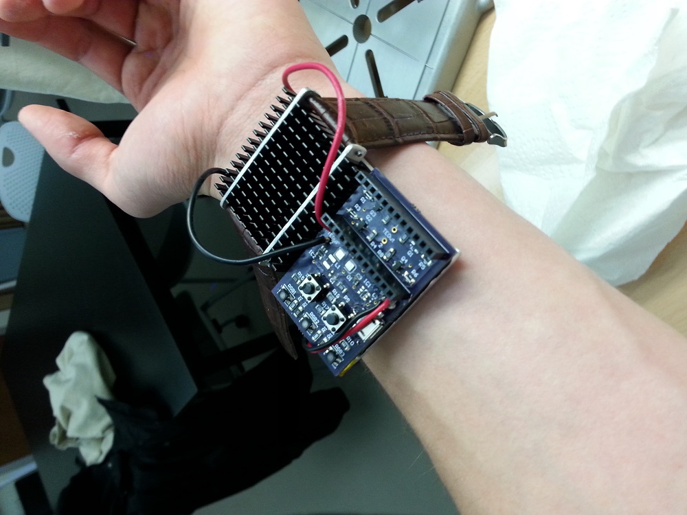
With this first prototype, I was able to meet the size constraints I placed so it would be actually practical to wear this device. I was also able to achieve pulsated cooling, but not heating due to a circuitry problem. It actually did cool me down in a uncomfortably warm environment so that’s the main reason why I would consider this first prototype to be a success.  I am also still working on ironing out the kinks with the six levels of heating and cooling.  Also, a lot of testing is required in order to find the optimal frequencies.

What were the largest hurdles you encountered?  How did you overcome these challenges?

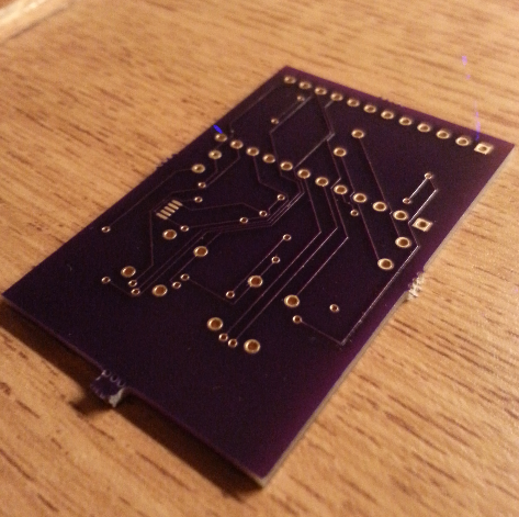
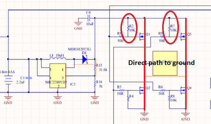
The largest hurdle I encountered was a short that I had on my PCB. It took me about two weeks to locate with the help of Professor Ponto. Originally, I thought it was a problem with the voltage boosting section of my circuitry that is needed in order to drive the thermoelectric cooler.  It turns out the problem was not with that section, but rather with the H-Bridge circuitry that enables a voltage to be applied across a load in either direction.  If you look at my electrical schematic below, the circled resistors should be pull-down resistors and connect the gate of the transistor to ground so when there is not a HIGH signal, the state of the transistor will not be floating.  But, as, you can see, they are currently connected to 5v, which activates both transistors and causes a direct path to ground.

Problem

Because I didn’t have enough time to redesign a second PCB by showcase, I made a compromise and removed those transistors so now the hardware was only capable of sending cool pulses.  Because I had fried the voltage boosting circuitry earlier, I had to add an external power supply (9v battery) to drive the thermoelectric cooler.

If you had more time, what would you do next? 

The first thing I would do next is redesign the PCB and change those resistor connections so they’re actually in a pull-down state instead of pull-up.  After ensuring cooling and heating is optimized, I would add a thermal conductor attached to the side of cooler that is in contact with the wrist to dissipate the heat more effectively.  Once I reach a prototype that is fully functional, I would like to perform some very scientific user tests with constant variables to see if the device actually makes a difference in improving comfort.  If the tests are successful, I will publish my findings in an academic paper.


12/7/2014 TEB Update

As the deadline approaches, the project is getting more and more stressful which was expected.  With that being said, it was quite the relief to test the board and see that there were no problems with the board that would require me to order another batch.  I am still on schedule and should be able to finish the complete prototype by this upcoming Friday.

  • What did you do this week?

This week, I continued to test the  functionality of the board with the code that I wrote.  Of course, testing comes with a lot of debugging so a good portion of my time was spent on solving problems involving my code and just ironing out the kinks of the program.

I also spent time over the weekend fabricating the mounts for attaching the watch band to the heatsink.  I was very pleased with the results.


  • Describe the problems you encountered

I encountered a number of problems this week, but luckily I was able to solve them quickly.

1) When I first powered my board, I noticed ‘magic smoke’ and disconnected the power supply.  I then realized that I had soldered my diode backwards, which had fried my boost converter chip

2) I noticed when testing the populated board with my multimeter that there was a short somewhere.  However, when I tested the unpopulated board, there was no short. I first thought that I may have accidentally bridged some pads during the surface mount soldering operation.  I inspected every component and ruled that cause out. I further deduced that this short was a result of soldering my diode backwards. It turns out there was an internal short within the boost converter chip so I removed the component and there was no short!

3) I forgot to place a power switch on the board when designing the PCB. To solve this, I had to solder the header sockets on the board and now to turn on the board, you just insert the microcontroller and that initializes the program.  When it is removed the board, no current is drawn.   However, because I had to solder these headers, that adds 1/4″ to the height of the unit

4) When testing my LEDs, they were not illuminating.  I took another look at the schematic and realized I mixed up the anode and cathode.  To solve this problem, I cut the common anode trace to negative and placed a jumper to the positive line and then I had to account for this in my code by pulling the pin LOW instead of HIGH to turn on the LED.

5) Next problem I had was with my code.  When testing the if the LEDs responded to the push buttons, I noticed only one button was working. Well, this turned out to be a bracketing issue.

6) The last problem was also with my code.  Finding an alternative day of performing a digitalWrite in the loop without using the ‘delay’ function.  If I used ‘delay’, the program ran very slow and often didn’t function. To solve this, I made use of the millis() function. You can see the code in the following link

https://docs.google.com/document/d/1rI2vCf5E__gzYc5JgFOSnOJRUpK55umKUBSVFD3ubfk/edit?usp=sharing

  • Are you on schedule?

Yes I am! I should be able to finish the complete prototype by Friday

  • Describe the successes you had

Like I said above, I was very pleased to find that there were no problems with my board that would require me to print another board.

I also was able to fabricate the physical device without any issues.

And also, after many hours of debugging, I wrote a program that works very well.

  • What do you plan to do next week?

Next week, I plan to wrap up the prototype and test if it actually gives you the perception of your body heating or cooling down. i will have to test many pulse frequencies to find the optimal one that is most effective.

Testing thermoelectric generator using photoelectric cells in series


Complete PCB for prototype 1


TEB Update 11/29/2014

  • What did you do this week?

For this week’s work, I soldered all the components onto the printed circuit board and to my surprise everything fit perfectly and went very smoothly.  Now in the coming weeks, we’ll see if everything actually works.

  • Describe the problems you encountered

One problem I faced was with the USB receptacle. The pins were so close together and I applied too much solder paste and as a result, there was a solder bridge between three pins.  This is an easy fix once I get my hands on some solder wick to remove some of that solder.

Another problem  I faced was that I realized I forgot to order four 56R resistors that connect to the gate of the MOSFETs. Now these resistors aren’t essential to the function of the circuit so  I just placed a wire across the resistor pads to close the circuit.

  • Describe the successes you had

One success I had was that all the footprints I custom designed fit the components perfectly.

Another success was the method I used for soldering the tiny surface mount components to the board. First, I applied solder paste to the pads of the components. Then, I very carefully placed the devices on the pads using a fine tweezers bent at a 45 degree angle. The solder paste kept the components in place because of its consistency. I then put them in a toaster oven, set the degrees to 450 Fahrenheit and waited two minutes.  I had no issues soldering.

  • Are you on schedule?

Yes I am on schedule. Now if my circuit has a problem where it will require me to resubmit a new PCB, then I will be behind schedule.

  • What do you plan to do next week?

Next week, I plan to perform tests to ensure the board is functioning properly and if it is, then I will be uploading code and will test it using the thermoelectric cooler.


1

2

4

3

TEB Update 11/23/2014

What did you do this week?

This week, I was not able to do much since I was still waiting for my board to arrive until yesterday.  When I received the board yesterday, I checked to make sure all the components fit on the custom footprints I created and they all did!

front

back

I also discussed with Professor Ponto and Jess (teacher assistant) how I will go about fabricating the wrist strap mounts that attach to the heat sink.  We came to the conclusion that bending square stock will be the best option with the resources I have available to me.

Describe the problems you encounter

No problems this week

Are you on schedule

Assuming I get the board assembled next week, then I am still ahead of schedule

What do you plan to do next week

Next week, I plan to solder the surface mount components to the board and perform a variety of different tests to ensure it is functioning as designed.

11/15/2014 TEB Update

  • What did you do this week? 

I received all my components from Sparkfun and Digikey, which can be seen below. You may be wondering whats in the syringes. One is thermal paste while the other is solder paste.

  Comp
Here are all the SMD components in their electrostatic discharge bags (too small to be photographed individually)
ESD components
I also soldered headers onto the microcontroller.

I wrote the program for device as well, which can be found here

  • Describe the problems you encountered

One challenge I ran into when soldering the headers  to the microcontroller board was ensuring that the headers were aligned perfectly perpendicular to the board.  This was very important because if they were not perpendicular, it may not fit in the socket on the custom PCB.  I solved this problem  by just soldering one pin to the PCB and then I could adjust it as needed by just applying heat to that one connection.

1

  • Describe the successes you had

One success I had was completing the program that the Thermoelectric Bracelet will run.  Professor Ponto verified that there weren’t any blatant errors so I consider that a success. Of course, there will most likely some small debugging errors that I will have to deal with, but the foundation is there.

  • Are you on schedule?

I am actually currently ahead of schedule because I initially overestimated the time it would take to ship my board. I received an email saying that three PCBs should be here on Friday.

  • What do you plan to do next week?

Next week, I plan to solder the surface mount components to the board and perform a variety of different tests to ensure it is functioning as designed.

11/8/2014 TEB Update

I spent this week reviewing my circuit design because this is a very complex board with traces everywhere so its very easy to make a mistake.  Luckily I did take a second look at it because I caught several faults that would have been detrimental to the functionality of the circuit. I’m hoping I caught all the errors, but realistically, I probably did not and will have to make another board.

With that said, I found this company called Oshpark that fabricates high quality PCBs for a very low cost. I ordered 3 PCBs for $13 including shipping which is phenomenal when it comes to PCB fabrication.  Granted my PCBs are only about an 1″ x 2″, that’s still an amazing deal.

Submitting the PCB was a process in itself.  I had to export all the required Gerber and drill files by Oshpark.

Upon doing that, I ordered all the components from Sparkfun and Digikey.


11/2/2014 TEB Update

Project Title–  TEB (Thermoelectric Bracelet) *name still in progress

Project Team Members- Jason Sylvestre

Description of what you are going to do- I will attempt to construct a working prototype that is capable of sending tailored thermal stimuli to the wrist using pulse width modulation (PWM) and a thermoelectric cooler. To adjust the temperature, you will use two push buttons to determine the frequency of the pulses and whether the pulses are cold or warm. There will be a RGB LED bar that corresponds to the pulse frequency and the thermal stimuli being sent.
Concept Art– Capture

Description of what inspired this project– Earlier this year, I read an article about a project engineered by some MIT students that was capable of sending regulated pulses of cold stimuli to the wrist to induce a perceptual change in body temperature.  It would essentially be a personal air conditioner. I thought I could improve this by making the device capable of sending both warm and cool stimuli to the wrist.

Description of Materials you plan to use along with the costs for these materials- Click here for the Bill of Materials

Steps/Timeline

10/28/2014- Finish complete design (electrical, 3D model, parts list, programming block diagram)

10/30/2014- Finish PCB design

11/11/2014- Assemble physical prototype (except PCB)

11/25/2014- SMT PCB board should be soldered and functioning

12/02/2014- Complete program that has been debugged

12/15/2014- Testing, Redesign, Implementation Complete

Backup Plans / Fallback plans

The part that I see most likely to fail is my circuit board design so as an extra precaution, I  have inserted extra vias into the PCB design in case there are faults.  My fallback plan is to assemble it on perfboard using through-hole components. I will also buy extra discrete components in case those fail.

Since the presentations, I have made great progress on the PCB design, which you can see below.   I designed this using Altium software.   As you may notice, it’s a very compact design.

PCB png

Thermoelectric Bracelet that Induces Perceptual Heating

This project is based off the Wristify from the MIT students, but rather instead of thermoelectric cooling it will perform thermoelectric heating.  The idea is that by sending pulses of heat at certain time intervals to the wrist, the brain is tricked into thinking the body is warming up when in reality, the temperature at your wrist is only changing a few degrees.  This phenomenon is similar to walking into a sauna.  At first, it appears that the environment is very hot, but then you get used to it and its fine.  What Im trying to accomplish with this project is analogous to walking into the sauna repeatedly at certain time intervals to give the perception that you’re heating up.  So this device will essentially act as a personal air conditioning unit.

I intend to work alone for this project

I am confident in my abilities to design and solder the accommodating circuitry for the project and write the code needed to send the pulses when two buttons are pressed(quite simple).  What I am a bit worried about is making it small enough so that it is actually practical and that people would wear it without interfering with motion. No one wants to walk around with a big cumbersome heatsink attached to their wrist.

Below is a block diagram of how the electronics would be connected

Block


LED Distance Graph

Description-  What I present before you is a simple2x4 LED bar graph that corresponds to the distance between a Sharp IR Digital  sensor and an object.  The range is between 0 and 10cm.  When you hit the fourth LED, the buzzer sounds indicating that is the maximum range.  There is a SPST switch that can be used to turn the buzzer on or off.  The resolution of the bar graph could easily be increased by simply adding more LEDs if you wanted more precise measurements

Inputs– Sharp IR distance sensor, SPST switch

Outputs– 8 Green LEDs, buzzer

Head Mounted Accelerometric Mouse Device (Assignment 4)

This would be a device for those who are physically paralyzed from the neck down or do not have motor functions in the arms and wrist.  Essentially, this would be a hat that can sense tilt of a person’s head using an accelerometer and send commands to a computer via USB to control a cursor similar to a joystick.   To click, the user bites down on a force sensor located in the person’s mouth.  The accommodating circuitry would be sewn to a hat of the user’s choice.

Some challenges one may encounter when pursuing this project include the accuracy of movements, calibration, and sensitivity to small head movements.

Screenshots_2014-10-07-14-51-39