This week I was working on the sewing the shift regiesters and leds to my dress. I will use two pattern in the picture below to sew the leds and I will use two blinking patterns that I found last week and speed of them. This week I did not had problems to solve these patterns without that I couldn’t control sewing speed because the dress is so long and the leds are very small. I think that the size of leds are the problems because they are really small so it will not be that recognizable when I have only some of leds. I think I am little bit behind on my sechedule because I think dealing with the shift register and accelerometer will take more time than I thought and I have no idea how to work throgh them by myself. My plan for next week is that I want to start programming the accelerometer and accelerometer with shift register together.
As the deadline approaches, the project is getting more and more stressful which was expected. With that being said, it was quite the relief to test the board and see that there were no problems with the board that would require me to order another batch. I am still on schedule and should be able to finish the complete prototype by this upcoming Friday.
What did you do this week?
This week, I continued to test the functionality of the board with the code that I wrote. Of course, testing comes with a lot of debugging so a good portion of my time was spent on solving problems involving my code and just ironing out the kinks of the program.
I also spent time over the weekend fabricating the mounts for attaching the watch band to the heatsink. I was very pleased with the results.
Describe the problems you encountered
I encountered a number of problems this week, but luckily I was able to solve them quickly.
1) When I first powered my board, I noticed ‘magic smoke’ and disconnected the power supply. I then realized that I had soldered my diode backwards, which had fried my boost converter chip
2) I noticed when testing the populated board with my multimeter that there was a short somewhere. However, when I tested the unpopulated board, there was no short. I first thought that I may have accidentally bridged some pads during the surface mount soldering operation. I inspected every component and ruled that cause out. I further deduced that this short was a result of soldering my diode backwards. It turns out there was an internal short within the boost converter chip so I removed the component and there was no short!
3) I forgot to place a power switch on the board when designing the PCB. To solve this, I had to solder the header sockets on the board and now to turn on the board, you just insert the microcontroller and that initializes the program. When it is removed the board, no current is drawn. However, because I had to solder these headers, that adds 1/4″ to the height of the unit
4) When testing my LEDs, they were not illuminating. I took another look at the schematic and realized I mixed up the anode and cathode. To solve this problem, I cut the common anode trace to negative and placed a jumper to the positive line and then I had to account for this in my code by pulling the pin LOW instead of HIGH to turn on the LED.
5) Next problem I had was with my code. When testing the if the LEDs responded to the push buttons, I noticed only one button was working. Well, this turned out to be a bracketing issue.
6) The last problem was also with my code. Finding an alternative day of performing a digitalWrite in the loop without using the ‘delay’ function. If I used ‘delay’, the program ran very slow and often didn’t function. To solve this, I made use of the millis() function. You can see the code in the following link
Yes I am! I should be able to finish the complete prototype by Friday
Describe the successes you had
Like I said above, I was very pleased to find that there were no problems with my board that would require me to print another board.
I also was able to fabricate the physical device without any issues.
And also, after many hours of debugging, I wrote a program that works very well.
What do you plan to do next week?
Next week, I plan to wrap up the prototype and test if it actually gives you the perception of your body heating or cooling down. i will have to test many pulse frequencies to find the optimal one that is most effective.
Testing thermoelectric generator using photoelectric cells in series
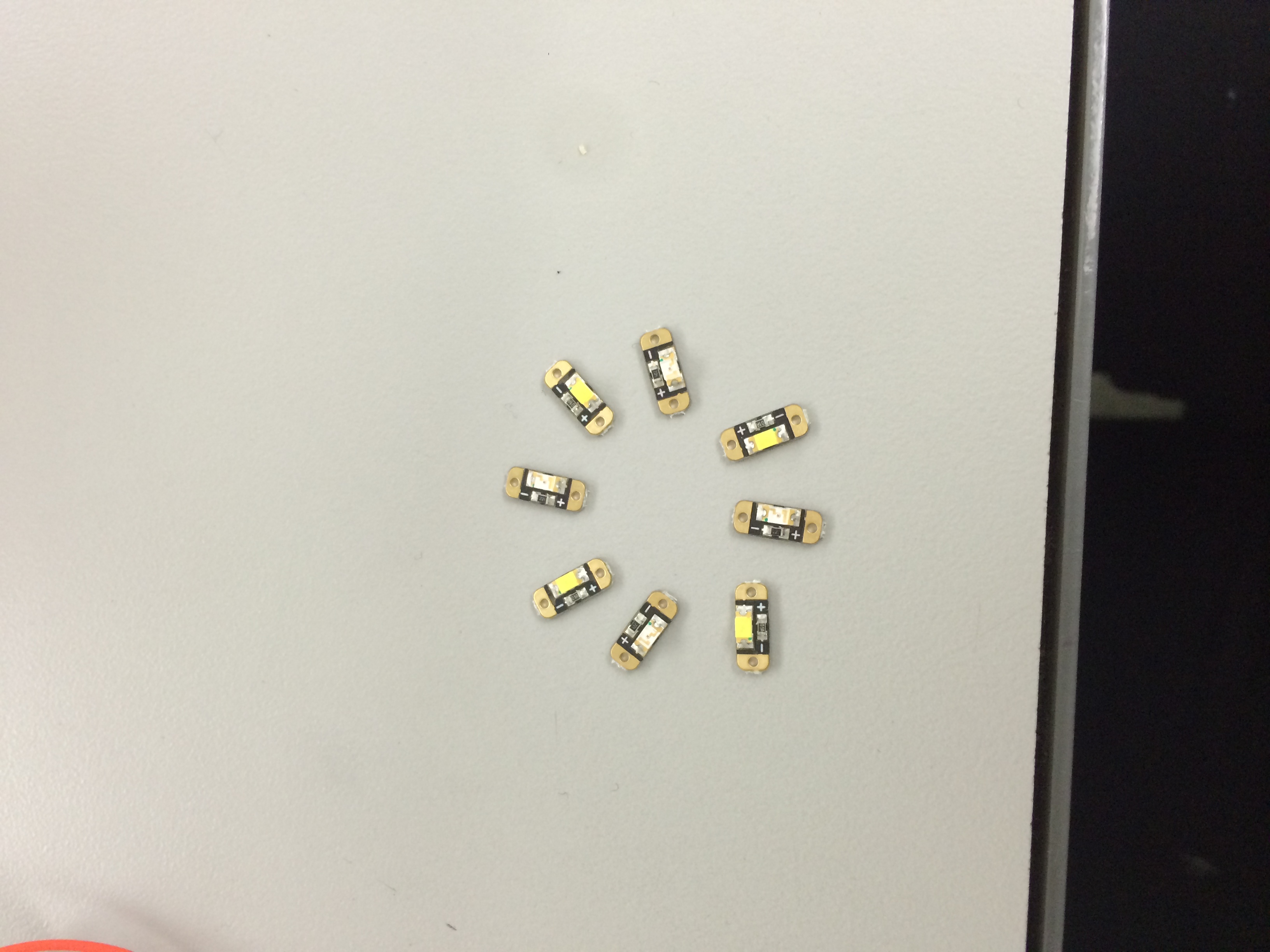
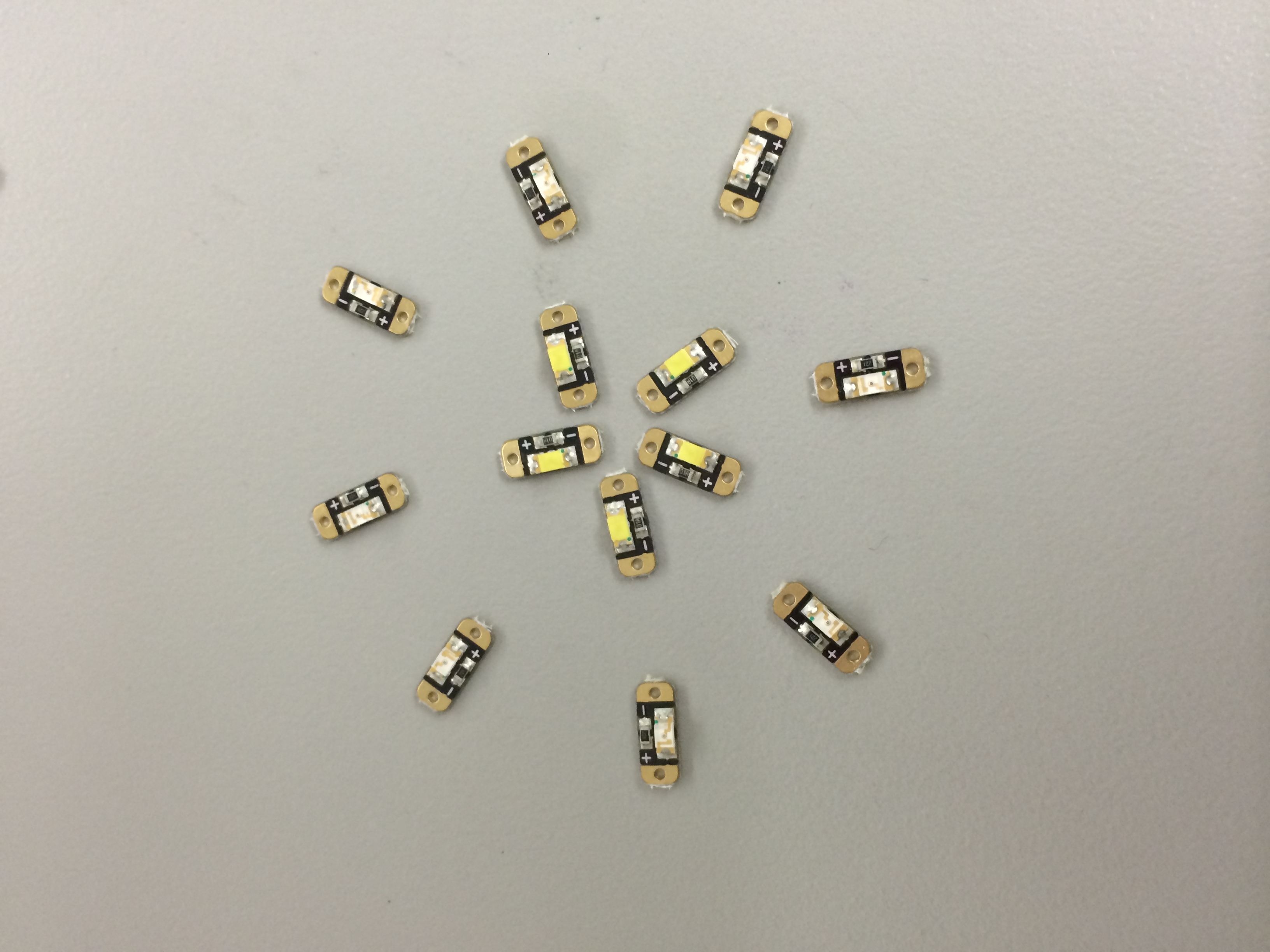
This week I was working on the “Shift Register” again. I was keep working same thing from the last week but added little more. I was founding how many leds can be light up with one shift register with the equal power and how many patterns that I can create from the shift regiester. Same as last week, I used the borad to connect the shift register, 8 leds together and the lilly pad. After I sew and connected each other, I run the program to see that it works or not. And I finally figured out that I can use two blinking patterns and speed of them. This week I did not had problems to solve these patterns without that I cannot control the leds individually. I think that it is the problems with the programming the code but, I don’t really know how to solve that problems. So, I think my dress will only have two blinking patterns with different speed. I think I am little bit behind on my sechedule because I think dealing with the shift register and accelerometer will take more time than I thought and I have no idea how to work throgh them by myself. My plan for next week is that I want to start programming the accelerometer and accelerometer with shift register together.
I was working on the “Shift Register” again. I was founding how many leds can be light up with one shift register because last week when I was working with the shift register, all the 8 leds aren’t turned on and when the leds truned on the power wasn’t equal between all the leds. Same as last week, I used the borad to connect the shift register, 8 leds together and the lilly pad. I wasn’t run the program because I just wanted to know how many leds can be light up equally with one shift register. So, I just connected to the computer for the power. The problem I had this week was that I might not able to make the pattern that I want to make because I cannot really control the leds individually. But, I finally figured out how to trun on all the leds equally. I think I am little bit behind on my sechedule becauseI think dealing with the shift register and accelerometer will take more time than I thought. My plan for next week is that I want to finish programming the shift register and start with the accelerometer.
We worked on the accelerometer, but we failed to understand what was the problem, the Bluetooth module and the smartphone app.
Describe the problems you encountered
I think the wiring in the accelerometer must have fried the circuit. The readings we are getting are very inconsistent and they do not make sense. I am afraid we are going to be behind schedule because of it, but hopefully we can work on other parts of the prototype while we wait for the new accelerometer.
Describe the successes you had
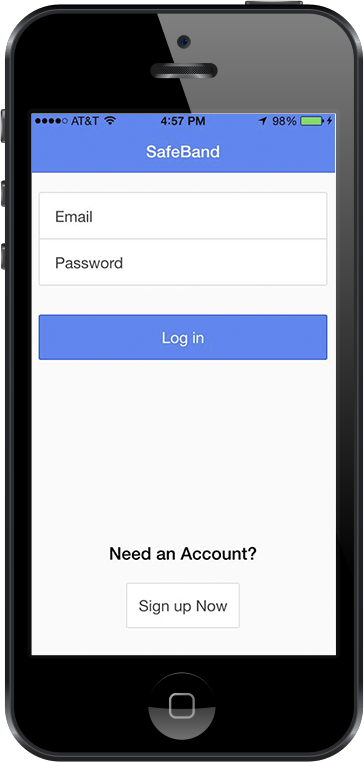
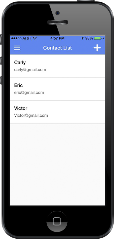
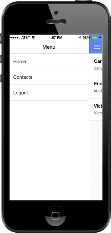
We found out how to connect the bluetooth module to the board and I began the testing with it. Victor worked heavily on the app and the functions Login, List Contact and Add Contact are working properly and he made sure they are connected with firebase as a backend framework
Are you on schedule?
It depends if the accelerometer is really fried or not. If it is we are will be delayed, but we can work on the app while we wait for the new piece and if it is not then we are on schedule.
What do you plan to do next week?
Probably order again a new accelerometer, sew the the bluetooth module after finishing the tests and send emails via bluetooh with the smartphone.
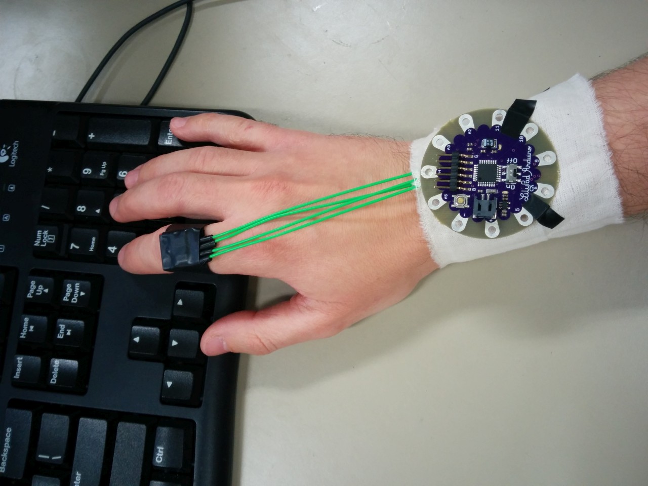
1) Got the IMU to work with my LilyPad, was able to get good Euler angle readings. Now we’re cookin’ with gas!
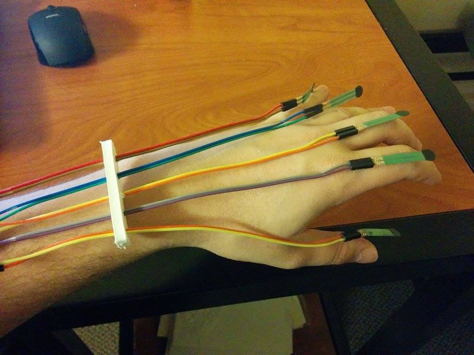
2) I started putting together a physical prototype of a wristband and IMU ring. You can see a physical mockup in the picture. Instead of using a flimsy piece of fabric for the wristband, tomorrow I plan to buy a sweatband and stitch my board and other components into it.
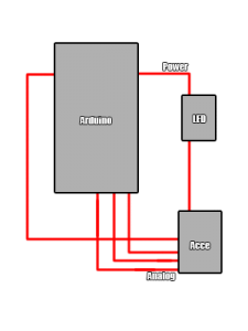
3) I’ve been experimenting with a neat little program called Gobetwino, which offers several useful features for communicating between an Arduino and a PC. I plan to use it for writing sensor data to a spreadsheet and analyzing the output, in order to derive activity and posture classification heuristics.
Current concerns:
1) I’m worried about wiring on the IMU. Specifically, I’m worried that connections might be too flimsy, which could cause the IMU to freeze periodically. I can’t think of a reliable solution, short of soldering the wires to the IMU, which I don’t want to do this early in development.
2) I’m also worried about wires being too thick and rigid, which could constrain the hand movement such that we get badly skewed sensor data for typing motion and posture. Anyone got any nicer, more flexible wires?
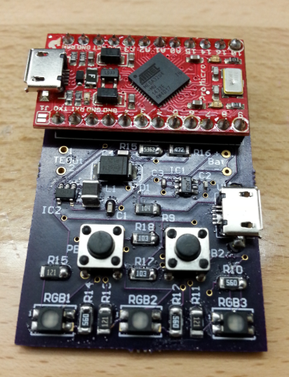
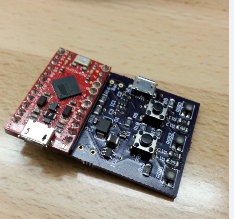
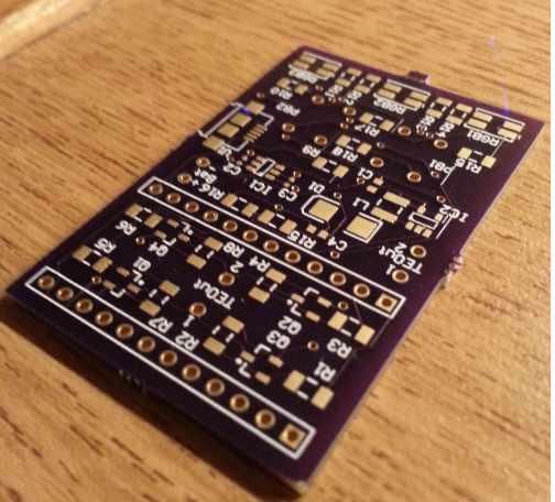
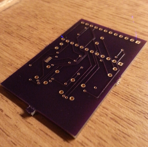
For this week’s work, I soldered all the components onto the printed circuit board and to my surprise everything fit perfectly and went very smoothly. Now in the coming weeks, we’ll see if everything actually works.
Describe the problems you encountered
One problem I faced was with the USB receptacle. The pins were so close together and I applied too much solder paste and as a result, there was a solder bridge between three pins. This is an easy fix once I get my hands on some solder wick to remove some of that solder.
Another problem I faced was that I realized I forgot to order four 56R resistors that connect to the gate of the MOSFETs. Now these resistors aren’t essential to the function of the circuit so I just placed a wire across the resistor pads to close the circuit.
Describe the successes you had
One success I had was that all the footprints I custom designed fit the components perfectly.
Another success was the method I used for soldering the tiny surface mount components to the board. First, I applied solder paste to the pads of the components. Then, I very carefully placed the devices on the pads using a fine tweezers bent at a 45 degree angle. The solder paste kept the components in place because of its consistency. I then put them in a toaster oven, set the degrees to 450 Fahrenheit and waited two minutes. I had no issues soldering.
Are you on schedule?
Yes I am on schedule. Now if my circuit has a problem where it will require me to resubmit a new PCB, then I will be behind schedule.
What do you plan to do next week?
Next week, I plan to perform tests to ensure the board is functioning properly and if it is, then I will be uploading code and will test it using the thermoelectric cooler.
We developed the hardware using the accelerometer and the software and its connection to the server.
Describe the problems you encountered
At first we were unsuccessful in wiring the accelerometer to the board.
Describe the successes you had
On Thursday class we learned how to wire the 3.3v accelerometer to the 5v Arduino by using a LED as a resistor.
The app is starting to connect to the server and is synchronizing contacts.
Are you on schedule?
We are a little bit delayed on the hardware end. But we are comprehending how things are supposed to work now and everything should be on schedule this next week.
What do you plan to do next week?
Wiring the Bluetooth and make the first messages appear on the smartphone app.
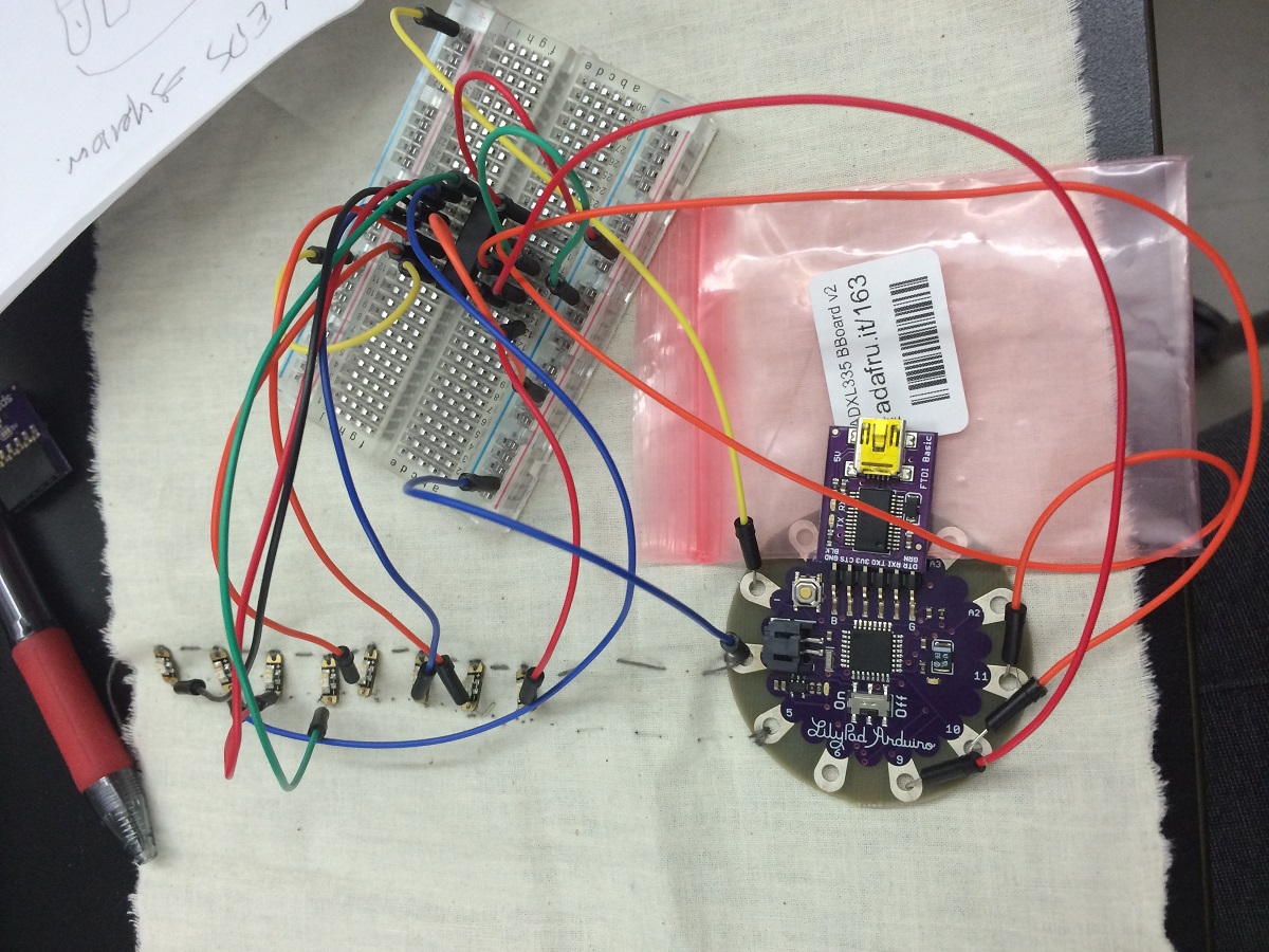
This week we solded the pressure sensors and ordered (again) the bluetooth pin that haven`t reached yet. In the picture below you can see how the pressure sensors were solded to the cables. The next step is to sew up the protection for the fingers which also contains the sensors so the player can press his finger agaisnt almost any surface. We also hope to start the software this week(the only obstacle will be create a program without the bluetooth board to test it).
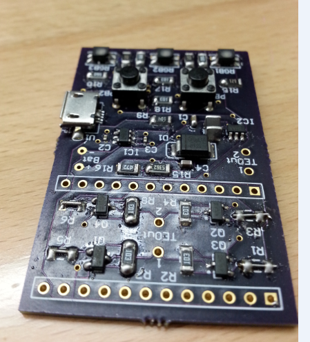
This week, I was not able to do much since I was still waiting for my board to arrive until yesterday. When I received the board yesterday, I checked to make sure all the components fit on the custom footprints I created and they all did!
I also discussed with Professor Ponto and Jess (teacher assistant) how I will go about fabricating the wrist strap mounts that attach to the heat sink. We came to the conclusion that bending square stock will be the best option with the resources I have available to me.
Describe the problems you encounter
No problems this week
Are you on schedule
Assuming I get the board assembled next week, then I am still ahead of schedule
What do you plan to do next week
Next week, I plan to solder the surface mount components to the board and perform a variety of different tests to ensure it is functioning as designed.