This project is a five-panel cap, with lights embedded in the brim, that reacts to an audio signal passed in through a standard 3.5mm headphone jack. As for how it works: it (mostly) doesn’t. Click the picture below for a feel of the current effect, then we can talk about why the video doesn’t demonstrate the above capabilities.

The warmup project this hat is based on took in an audio signal from a headphone cable, broke it up into audio channels, and tied the intensity of each LED to the presence (or absence) of a particular channel. However, the hat had batteries taped to the forehead and wires everywhere. The effect was interesting, but not very wearable. The focus of this project was to make the previous implementation as sleek and non-obvious as possible.

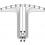
To make this happen, I settled on three specific improvements. Firstly, instead of wires on top of the hat connecting the LEDs together, I planned on creating a flexible circuit to attach on top of a pre-existing brim, just under the fabric. Secondly, I planned on making the hat myself so that I could better hide the tech I couldn’t minimize. Thirdly and lastly, I intended to offload as much of the electronics as I could to a separate board, which would communicate wirelessly with the hat.
From the video above, the most conspicuous absence of functionality is the lack of reaction to an audio signal. The warmup project had this fully implemented, and in fact this project does as well. However, there’s no way to use that information. At least one of the RF modules responsible for transmitting the data is fried (they were working in testing, but after construction stopped responding). I failed to identify this as the weak link in the chain when planning the project, and without a backup plan, this single point of failure limits effect of the entire project.
The creation of the flexible circuit posed a significant problem. The standard technique involves ironing on a toner-based resist and dunking the copper in a chemical etchant. This broke down when it came to applying the toner. The traces I needed were rather small, due to using really tiny components, and they kept on breaking or not transferring well. The resist went through several iterations. The most notable change was increasing the width of the traces and adding larger fill planes. This didn’t seem to help at all, sadly. In the end I had to scrap the flexible board and construct my own brim from cardboard and thin plastic, which allowed me to embed all the electronics I needed in cavities in the cardboard.
I’ll admit to being somewhat disappointed with the outcome of this project. I could work around the lack of a flexible board (although that is still frustrating), but my planning mistake with the RF modules removed any chance of actually responding from an input signal. Some parts definitely turned out well, however. I’m quite pleased with most of the sewing portion of this hat. There’s also some clever work in the brim that is totally hidden by fabric and glue that I’m proud of.
There’s a lot more work that can be done to this project with more time and resources. Getting the RF modules to work would be an obvious first step. However, they might be able to be replaced with other types of wireless communication – WiFi and Bluetooth Classic are the most immediate choices. More exploration on the toner transfer method for PCB fabrication might lead to more success. In particular, we might try dedicated toner transfer paper, printing directly on the copper, a laminator to apply the toner, or even going to a fab house to outsource part of the fabrication.
The final poster is available here.