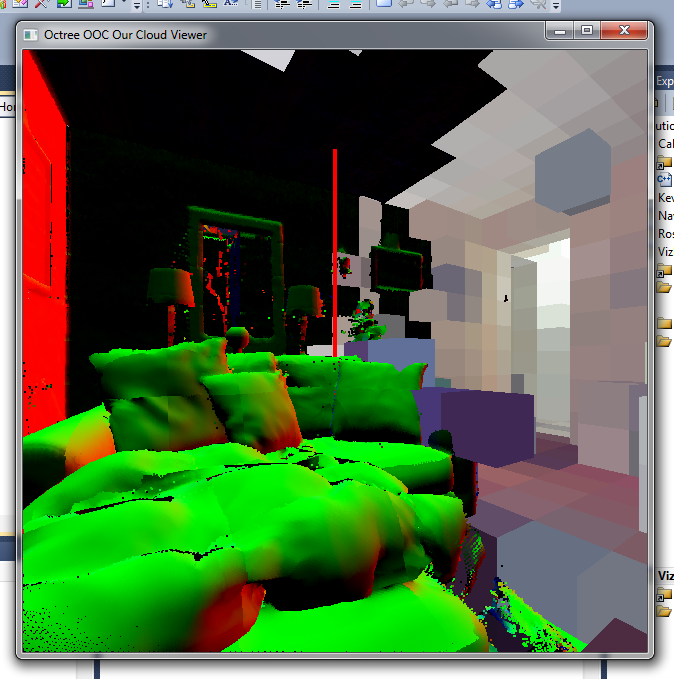
Low-resolution normals
Normals and their respective point radius are now stored as 8-bit signed chars and converted to floats when uploaded to the GPU. This seems to faster than storing everything as floats and it requires only a quarter of the memory which makes file loading faster as well.
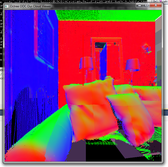
There was also quite a headscratching bug in there. I transfer the normals+radius for each point as a signed character vec4. You cannot normalize this to 0..1 as this mixes both values. Instead, the normal was extracted from the first three components and normalized (the easy part) but the radius has to be manually divided by 127 in the shader to get the correct value. The result can then be multiplied by the predetermined max splat radius.
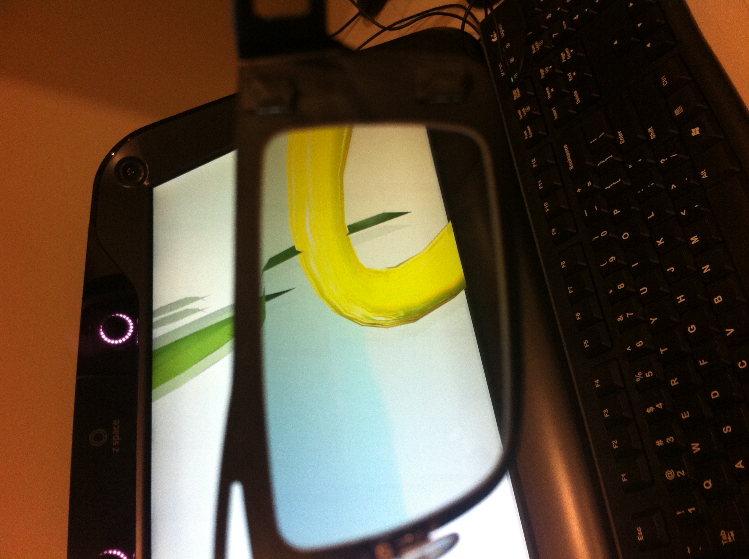
Point sprites (left) vs splats (right)
Performance
I found two major problems with the splatting:
- Splatting is very sensitive to normal changes, whereas point sprites (in our current implementation) are spheres and therefore rotation invariant. Normal calculation is in effect an estimation and it can be _way_ off leading to rendering artifacts.In theory it should provide a smooth surface as the splats are oriented along the normals as opposed to the organic, `bubbly’ surface of point sprites. When looking at the example figures in the splatting papers, it looks like the models/point clouds chosen quite carefully or prepared rather well with no outliers of the dataset and continuous surfaces. I found out that normal estimation breaks down at these points which becomes very noticeable with splats, moreso than with point sprites.
Even worse, when splats are oriented at a `wrong’ angle it is possible to actually create holes in surfaces, as the splats are oriented the wrong way. - When enabling splatting framerate drops noticeably from about 40 FPS for point sprites to 15 for splatting (without online calculation). It seems to me that the increased number of primitives created in the geometry shader maxes out the pipeline.
However, gDebugger shows no increased number of primitives created (maybe it cannot inspect that `deep’) and my understanding of point sprites is that they are a `default’/hardware geometry shader (at least in their functionality) that turn points into textured quads.
Furthermore, as splats are point samples, the fragment shader currently discards all fragments that do not lie within the circle described by the point sprite. This seem to decrease frame rate even further?
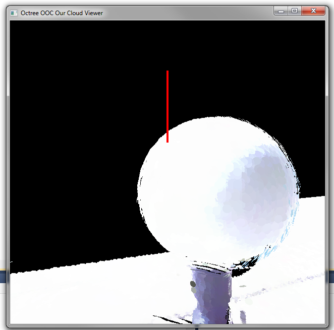
Splatting silhouette of a sphere
Results
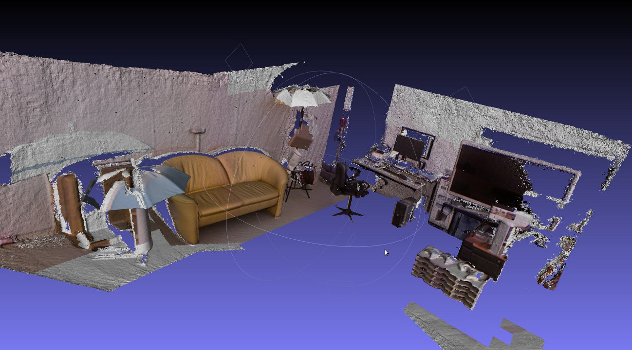
Quality improvements are mostly visible very close-up and along planar surfaces, eg walls and silhouettes, eg window frames. However, considering the perfomance hit it is questionable whether this slight increase in quality is worth the effort. I noticed that some moiree patterns got worse at mid and long range, probably due to splats oriented at an oblique angle.
Overall I would rather implement a LOD scheme with points and point sprites: at close distances, (< 1-1.5m) the point sprite shader should be used to fill all the gaps. Everything beyond that distance already appears solid due to the high density of points even when rendering points at size 1.0.