URL : https://filelocker.discovery.wisc.edu/public_download?shareId=af0daed307f9c66123e3843360f328c8
Password : ReKinStruct

URL : https://filelocker.discovery.wisc.edu/public_download?shareId=af0daed307f9c66123e3843360f328c8
Password : ReKinStruct
I have tried thinking of other datasets that can be obtained with the Kinect Snapshot program. A few interesting ones are a candle burning down, a fast growing plant, melting ice cream, etc. I have uploaded a PCD dataset of a person walking. I will be uploading similar datasets in the days to come.
Link to DatasetA: https://filelocker.discovery.wisc.edu/public_download?shareId=af0daed307f9c66123e3843360f328c8
If it asks for a password, it is ReKinStruct
Meanwhile, I have been thinking about next steps to do with the Kinect and one of the ideas that I have in mind is using two Kinects to obtain these datasets. This way, a lot of points would get filled for the scenario where it is full of shadows now. The concept image looks something like this.
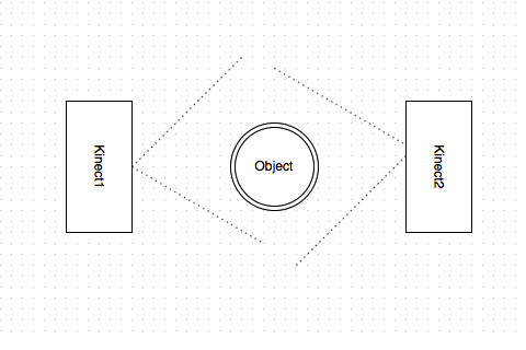
This way I would even get the dark side of the object. There are a few limitations to using two Kinects like interference of the speckle pattern. I am going to hide one Kinect from the other to avoid these effects. Working on setting up two Kinects and will upload some datasets this week.!
The video posted below demonstrates what how the leap motion looks in the world builder application. My next step will to be to start adding gestures to manipulate the object that the user makes. I expect it to be a challenge to have the leap motion correctly detect all five fingers, so gestures will need to use 1-3 fingers. (Video to come in the next hour, free Vimeo accounts make you wait to “convert” the file).
The first gesture I want to implement is this:
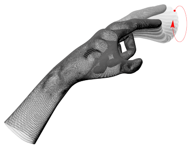
And heres the documentation: https://developer.leapmotion.com/documentation/python/api/Leap.CircleGesture.html
I think this would be one of the easier gestures to test because it has a starting point with one finger and an ending point with one finger. By just using one finger it will be easier to test implement as opposed to using multiple fingers for a gesture.
I will be updating this post through out the week with my progress.
And heres a cool video I found on dynamic shape display just for fun: https://www.youtube.com/watch?v=5EkkTV51Pg0
Paramecia Test
The image works as the preview on my computer (when using my external hard drive as a source for the images – I tried storing images directly on my computer but there was not enough room, so the hard drive is necessary)
I don’t think I’m telling it to look in the correct place for the images… Files are uploaded to Box.com, in folders for the different zoom levels:

Here is the code I am using:
html, body, #map-canvas {
height: 100%;
margin: 0px;
padding: 0px
}
var moonTypeOptions = {
getTileUrl: function(coord, zoom) {
var normalizedCoord = getNormalizedCoord(coord, zoom);
if (!normalizedCoord) {
return null;
}
var bound = Math.pow(2, zoom);
return ‘https://app.box.com/files/0/f/1814786029/InfocusAnatomy_Paramecium‘ +
‘/’ + zoom + ‘/’ + normalizedCoord.x + ‘/’ +
normalizedCoord.x + ‘.jpg’;
},
tileSize: new google.maps.Size(256, 256),
maxZoom: 8,
minZoom: 0,
radius: 32768,
name: ‘Moon’
};
var moonMapType = new google.maps.ImageMapType(moonTypeOptions);
function initialize() {
var myLatlng = new google.maps.LatLng(0, 0);
var mapOptions = {
center: myLatlng,
zoom: 1,
streetViewControl: false,
mapTypeControlOptions: {
mapTypeIds: [‘moon’]
}
};
var map = new google.maps.Map(document.getElementById(‘map-canvas’),
mapOptions);
map.mapTypes.set(‘moon’, moonMapType);
map.setMapTypeId(‘moon’);
}
// Normalizes the coords that tiles repeat across the x axis (horizontally)
// like the standard Google map tiles.
function getNormalizedCoord(coord, zoom) {
var y = coord.y;
var x = coord.x;
// tile range in one direction range is dependent on zoom level
// 0 = 1 tile, 1 = 2 tiles, 2 = 4 tiles, 3 = 8 tiles, etc
var tileRange = 1 << zoom;
// don’t repeat across y-axis (vertically)
if (y = tileRange) {
return null;
}
// repeat across x-axis
if (x = tileRange) {
//x = (x % tileRange + tileRange) % tileRange;
return null;
}
return {
x: x,
y: y
};
}
google.maps.event.addDomListener(window, ‘load’, initialize);
Box.com is much better than the original “mywebspace” from UW, with more storage and a much more streamlined uploading system. It does log out periodically, but it is easier to go back and find where I need to pick back up, especially now that the tile images sorted into folders instead of one massive conglomeration.
Cricket is also in progress, and Onion is being re=done, with better representations of cellular organization as far as root nutrient absorption. Even though the onion was supposed to just be a test, I want it to be fully rendered instead.
It’s been a while, but projects are still in the works.
At the present zoom level (with final image 32k x 32k pixels) the simplistic cellular structures that I had originally made for the onion are not large enough to quite convey the complex interactions that are happening with nutrient exchange and transportation, so I think this needs to get bumped up to 64k pixels… or change the zoom level to reflect a greater zoom than is actually represented (not my preferred route).
Grouping the tiles as jpegs within folders rather than as one massive lump sum has made uploading to Box much easier: each “zoom level” has its own separate group, so if an upload is interrupted, it is much easier to see where it needs to be resumed. The largest folder takes about 12 hours to upload, exponentially decreasing the loading time as folders become smaller.
In order to get additional direct source imagery specific to the items I am working on, I am constructing a low-tech travel-sized microscope-camera based on the designs shown in this video:
He has specific instructions here here as well.
I met the designer/inventor Kenji Yoshino through a friend of mine: Molly Rideout, who runs the artist residency Grin City Collective in Grinnell, Iowa. He was a resident artist there last summer and (among many of his creative endeavors) developed this microscope with the intention of making it a resource for doing work in various settings, as well as providing alternative options for schools or programs that do not have access to higher end microscopes. Many thanks to him for posting the instructions as a resource!
I will be picking up the plexiglass today, and hopefully constructing it after work! Having the flexibility to take images of what I am seeing through the microscope will save time when rendering the more detailed aspects of these drawings. The pictures won’t be the best, most amazing quality (I only have an iPod-touch that I will use to capture photos) but their primary use is for reference material, so I don’t have to draw with one eyeball glued to the eyepiece. The university has incredible imaging cameras as well, that can take really amazing high-resolution photographs, as well as more sophisticated view-screen microscopes with various capabilities (I am quite enamored of these and would love to have one sometime in the distant future) – but for my purposes, I am okay with this for now.
I scanned the concrete pillar in my office to see if we get resolution high enough to investigate small details — in this case the air bubbles and enclosures in the concrete, in the proposed project bullet holes and dents.
The distance between scanner and surface was about 1 foot and only a single scan was taken. In the scanner software I selected a small window. Unfortunately, the scanner does not tell which coordinate system this is based on, so I had to eyeball it. For further reference, this is how I think it looks:
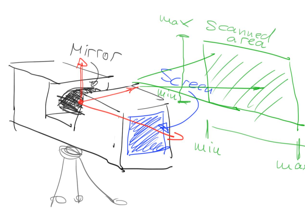
Scanner coordinate system.
The scanning was set to the highest resolution and quality (4x supersampling?) settings and took about an hour — this is really only practical if we want to scan such a small area. Imported into SCENE, it shows up as about a one square-foot area containing about 24 million points:
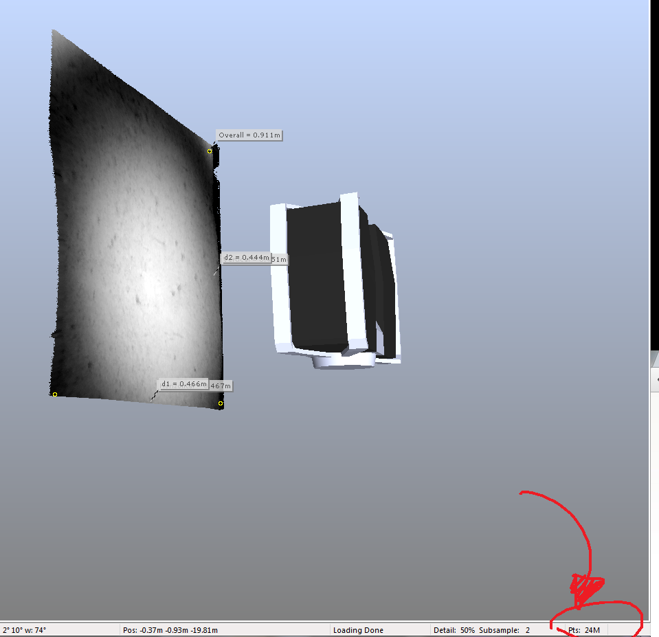
High resolution scan in SCENE.
The scan dataset is about 700MB in size. We get a theoretical resolution of 24M/(400*400)mm2 = 150 pts/mm2. That seems rather high. Note that with multiple scans and interleaved scan points this number would increase further.
On a similar note, SCENE breaks down at these small scales (I think it’s more designed for surveying) and has problems displaying them, even after setting the near plane to 0.01. Movement is also way too coarse to be useful at these small scales. This is as close as we can go:
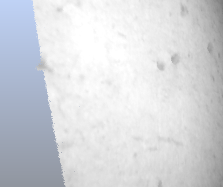
Scene close up (looks like the moon surface)
The next steps will be exporting this data and displaying it with our software. Maybe it will be useful starting a small PCL close-up viewer, as the current octree generation is between 0.25m and 0.3m and would therefore put all points in a single voxel. An alternative could be increasing the scale of the scan data and multiplying the coordinates of all points by a fixed scale, eg. 100. That could create an octree hierarchy and we could use our out-of-core viewer for this data as well (plus all the other VR displays).
So, like I said in the last post, I had got the Kinect to obtain and view point cloud data but only manually. I updated the code a bit to do the above without intervention. Here is the link to the video of a time varying PCD that I obtained.
YouTube link : http://youtu.be/T4IPKq0rGII
Yes, that is me walking like a zombie. Note that I have loaded the points as PointXYZ on purpose to give a feel of the pointcloud. Loading the points as PointXYZRGBA feels like a picture and not a pointcloud.
The idea behind this is 8 PCD files named output1.pcd, output2.pcd and so on. The ReKinStruct_Snapshot.cpp code would take a snapshot once every second and save as binary PCD files with names as listed above. The Binary PCD files are constant in size (4801 KB).
The ReKinStruct_Viewer.cpp loads these files and displays them in sequence with a time delay of 1 second. It uses two pcl::PointXYZ pointers. One loads the output<even>.pcd files and the other loads the output<odd>.pcd files. So when the even-pointer is displaying the point cloud in the viewer, the odd-pointer loads the next .pcd file in the background and vice versa thus abstracting the user from the latency of loading the files.
And for some reason, Visual Studio 2010 didn’t let me use Sleep() or wait() routines. So I had to write my own API as follows.
#include <time.h>
void wait(unsigned int seconds)
{
clock_t timeToWait = clock () + seconds * CLOCKS_PER_SEC ;
while (clock() < timeToWait);
}
Next steps would be to obtain a faster scenario and progress through the 3D viewer faster, like real-time motion.
Will keep you posted.!
Last week was quite busy for me, but I did begin sketching out ideas for the UI with when everything is attached to the world builder (stylus & leap motion).
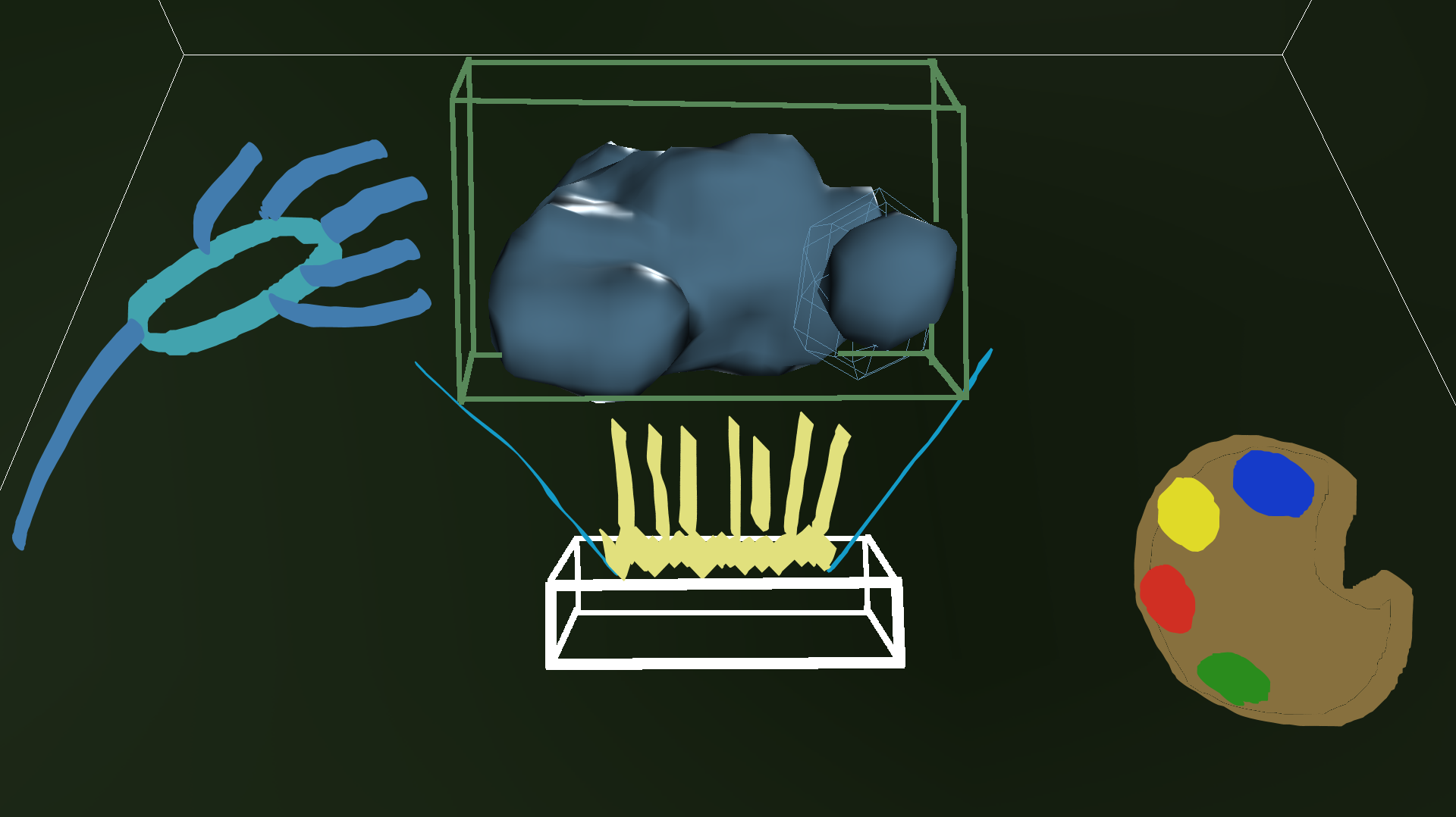
I wanted to keep things simple so instead of using two hands with the leap motion, I believe using one hand to rotate (left hand) and one hand to draw/color (right hand) makes the most sense. The left hand would be used to rotate the object on the xyz plane. The right hand, which holds the stylus, is used to pick colors and draw shapes.
Something I see potentialy being a problem is implementing the select object function. The Leap Motion is pretty insensitive and does not always map the fingers properly. I believe a two finger pinching motion (similar to zoom function on smart phones) and then rotating the wrist which subsequently rotates the object would be the best approach for this function.
Edit 4/3/13
Was able to get world builder to detect the leap motion so I am making progress in that area. In order to get the leap motion to detect, I had to use skeletal viewer once again. Now world builder seems to halt all of its functionality (drawing, head tracking, etc) but a valid hand is being tracked by the leap. This will be the next problem to tackle.
Edit 4/6/13
Hands are now showing in world builder from the leap motion. Currently the leap motion will only show hands when the skeletalViewer is selected. This week I will be working on adding the leap motion functions into the world builder application so that it is not dependent upon the skeletalViewer.
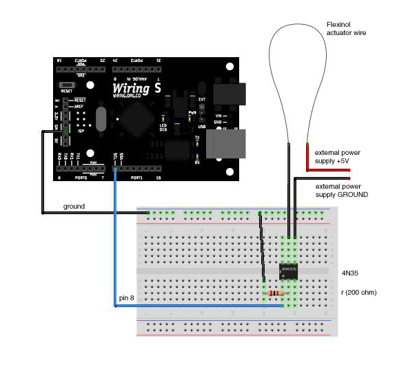
Unfortunately, not much progress has been made this week. I’ve ordered some additional Flexinol in longer lengths and I can’t really do any additional tests until it arrives.
In the mean time, I have purchased smaller gauge music wire that I think will work well for the spring mechanism. I’ve also done some research on how I can run the Flexinol using an Arduino:
 I also assembled a more complete presentation on the installation: